Serpentine
This item checks all symmetry items for uniformity of the differential pairs design environments.
Differential signaling is a powerful tool used to design high-speed digital buses
that dramatically reduces the amount of common-mode noise seen at the receiver,
which allows higher data rates to be realized. Differential pairs must have the same
environment to keep a stable signal and coupling status in terms of trace length,
trace width and routing structure including vias and passive components. Therefore,
designers should carefully design symmetry between two signals to achieve the best
signal quality not only for a single net but also for a differential pair
net.
- Item Name: Input item name.
- Net: Define net group for serpentine check.
- Filter: Enter a filter to choose differential pair net from selected net group. After entering a base net and pair net click Add Filter. If this field is empty, the DFE considers Net Group as a single-ended net.
- Start Component: Define start component. This component is used for Symmetry Check only.
- Pin Escape: Enter a radius of circular region around pins to be excluded for the rule check.
- Symmetry Check
- Serpentine Start Point Check: Allowable maximum length between serpentine position and Start Component.
- Discrete Component Symmetry Check: Allowable maximum placement skew between passive components which are connected to differential signals.
- Via Symmetry Check: Allowable maximum distance between (+) and (-) vias of differential pair net.
- Via Length Check: Allowable maximum placement skew between vias which are used for differential signal pairs.
- Component Existence Check: Check if other components exist between differential pairs.
- Bending Shape Check
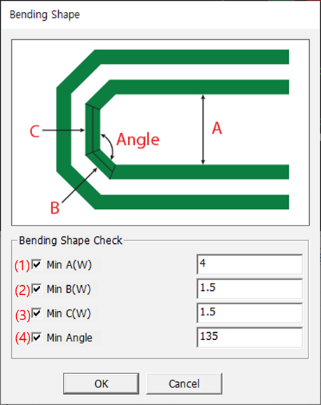 Figure 1.
 - Min A(W): Required minimum separation between bending trace.
- Min B(W): Allowable maximum length of segment “B”.
- Min C(W): Allowable maximum length of segment “C”.
- Min Angle: Required minimum trace angle.
- Serpentine Shape Check
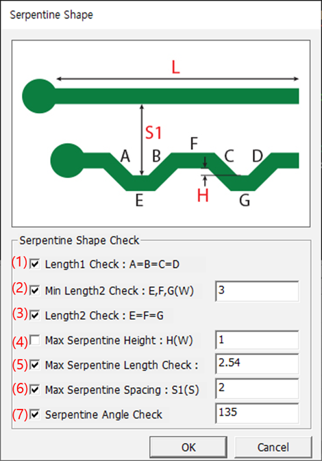 Figure 2.
 - Length1 Check A = B = C = D: Allowable maximum length of segment A, B, C, D.
- Min Length2 Check: E, F, G (W): Allowable minimum length of E, F, G.
- Length2 Check: E = F = G: Allowable maximum length of segment E, F, G.
- Max Serpentine Height: H (W): Allowable maximum height of serpentine trace.
- Max Serpentine Length Check: Allowable maximum length of total serpentine.
- Max Serpentine Spacing: S1(S): Allowable maximum separation of serpentine.
- Serpentine Angle Check: Required minimum trace angle.