Length
This rule checks for a trace length violation.
Signal trace length is a dominant factor that affects delay. Improper trace length
results in unexpected delay or different phase of waveform during signal
transmitting. Increased trace length leads to a greater inductance that causes a
waveform deformation. For timing consideration, trace length matching will be
necessary even if it increases the length. This rule checks electrical skew and
routing efficiency.
- Item: Input item name.
- Test Item: Define test item.
- Net Length Check: Checks the total length of specified net. You also
can check the length of the specified net between start component
and end component.

Figure 1. - Pin-to-Pin Length Check: Checks the pin to pin length of specified
net.

Figure 2. - Net Ratio Check (Net1/(Net1+Net2)): Checks the ratio of net1 with
net2.
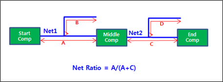
Figure 3. - Branch Ratio Check (Branch1/(Branch1+Branch2): Checks the ratio of
branchlength1 with branch length2.

Figure 4.
- Net Length Check: Checks the total length of specified net. You also
can check the length of the specified net between start component
and end component.
- Net1: Select a target net group.
- Start Component/End Component: A test is performed between the start component and the end component.
- Component Keep IN/OUT: Define the test region. For example, you can test
inside or outside the breakout region of CPU with different test
values.
- Component Group: Select the required component group which is used for defining the test region.
- Region: Define the required test region.
- IN: Test inside of the breakout region of target component.
- OUT: Test outside of the breakout region of target component.
- Range (COC+distance): Enter the distance value to define breakout range. The COC (Component Overlap Check) plus this distance value is considered the test range.
Net Length Check
Define the test parameter for Length Check.
- Check Length L: Assign a reference length.
- Tolerance (%): Define allowable tolerance ratio of length difference compared to the reference length.
- Check Type: Select a length check criteria type between Min, Max and Range.
- Max: Total length should be less than Check Length L + Tolerance.
- Min: Total length should be longer than Check Length L – Tolerance.
- Range: Total length should be between Check Length L – Tolerance and Check Length L + Tolerance.
- Manhattan Ratio Check: Check length ratio between routing length and
manhattans length.
- Allowable Ratio (%): Assign the required ratio. If total routing length of net is Between Manhattan Length * (1-Ratio/100) and Manhattan Length *(1+Ratio/100), it reports as passed.
- Middle Component
- Component: Specify the middle component.
- Exclude Component: Specify the component should be excluded.
- Net2: Specify middle net.
- Options
- Include VIA Length: The length of via will be added to the total trace length value.
- Copper Length Compensation: If copper is included in trace, choose a
copper Polygon length measuring method between Exclude, Manhattan
Distance, and Minimum Distance.
Exclude: Ignore copper length.
Manhattan Distance: Use Manhattan distance for copper length value.
Min Distance: Use minimum distance for copper length.
Figure 5.
Pin-to-Pin Length Check
Define the test parameter for Pin-to-Pin Length Check.
- Check Length L: Assign a reference length.
- Tolerance (%): Define allowable tolerance ratio of length difference compared to the reference length.
- Check Type: Select a length check criteria type between Min, Max and Range.
- Max: Total length should be less than Check Length L + Tolerance.
- Min: Total length should be longer than Check Length L – Tolerance.
- Range: Total length should be between Check Length L – Tolerance and Check Length L + Tolerance.
- Manhattan Ratio Check: Check length ratio between routing length and
manhattans length.
- Allowable Ratio (%): Assign the required ratio. If total routing length of net is Between Manhattan Length * (1-Ratio/100) and Manhattan Length *(1+Ratio/100), it reports as passed.
- Start Pin: Specify start pin of net.
- Click required component group from Component Group List.
- Click the arrow. All components that belong to that group are listed.
- Assign required pin number into Select Pins column.
- Select required pins and click OK to close this dialog.
-
End Pin: Specify start pin of net.
- Click the required component group from the Component Group List.
- Click the arrow. All of the components that belong to that group are listed.
- Assign required pin number in the Select Pins column.
- Select required pins and click OK to close this dialog.
- Options
- Include VIA Length: The length of via is added to total trace length value.
- Copper Length Compensation: If copper is included in trace, choose a copper polygon length measuring method between Exclude, Manhattan Distance and Minimum Distance.
- Exclude: Ignore copper length.
- Manhattan Distance: Use Manhattan distance for copper length value.
- Min Distance: Use minimum distance for copper length.
Figure 6.
Net Ratio Check
Define the test parameter for Net Ratio Check.
- Net Ratio Check (Ratio = Net1/(Net1+Net2))
- Check Ratio: Assign the required ratio.
- Check Type: Select a net ratio check criteria type between Min and Max.
- Middle Component:
- Component: Specify middle component.
- Exclude Component: Specify the component that should be excluded.
- Net2: Specify middle net.
- Options
- Include VIA Length: The length of via will be added to the total trace length value.
- Copper Length Compensation: If copper is included in trace, choose a copper polygon length measuring method between Exclude, Manhattan Distance, and Minimum Distance.
- Exclude: Ignore copper length.
- Manhattan Distance: Use Manhattan distance for copper length value.
- Min Distance: Use minimum distance for copper length.
Figure 7.
Branch Ratio Check
Define test parameter for Branch Ratio Check.
- Branch Ratio Check (Ratio = Branch1/(Branch1+Branch2))
- Check Ratio: Assign the required ratio.
- Check Type: Select a net ratio check criteria type between Min and Max.
- Middle Component:
- Component: Specify middle component.
- Exclude Component: Specify the component that should be excluded.
- Options
- Branch2 measure base: If passive components exist in net, you can
assign branch2 measure reference.
- From first passive component to middle component: The branch
length2 is measured from first passive component to middle
component.

Figure 8. - From last passive component to middle component: The branch
length2 is measured from last passive component to middle
component.

Figure 9.
- From first passive component to middle component: The branch
length2 is measured from first passive component to middle
component.
- Copper Length Compensation: If copper is included in trace, choose a
copper polygon length measuring method between Exclude, Manhattan
Distance and Minimum Distance.
- Exclude: Ignore copper length.
- Manhattan Distance: Use Manhattan distance for copper length value.
- Min Distance: Use minimum distance for copper length.
Figure 10.
- Branch2 measure base: If passive components exist in net, you can
assign branch2 measure reference.