Bus
BUS is a bundle of signals that have the same signal attributes. DATA and ADDRESS lines are examples of BUS. In order to keep the same signal attributes, they have the same length, width and via. This DFE item checks BUS lines for the uniformity of their length, width and via structure.
- Make lengths the same to make equal transmission speed (delay).
- Make pattern widths the same to match impedances.
- Make the number of via usage the same.
- Item: Input item name.
- Net: Select a target net group.
- Check Type: Select a length check criterion.
- Not Check: Do not check trace length.
- Min: Check if trace length is shorter than base value ④.
- Max: Check if trace length is longer that base value ④.
- Range: Check if trace length is within specific range.
- Ratio Base: ④*(1-⑦/100) ~ ④*(1+⑦/100)
- Value Base: ④-⑦ ~ ④+⑦
- Shortest Net Base: Test all net length with shortest net’s trace length.
- Combination Length: In case of daisy-chain topology multi-load
system, it checks if trace length of all possible path longer than
Shortest net length + ⑦. It will check trace length of path 1, 2 and
3 respectively.
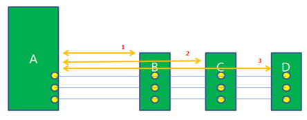
Figure 1. - Combination Length2: In case of tree topology multi-load system, it
checks if trace length of all possible path longer than Shortest net
length + ⑦. It will compare trace length of path 1, 2 and 3.
(1=2=3)
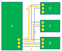
Figure 2. - T-Branch Symmetry: In case of tree topology multi-load system, it
checks if all the trace length from driver to load have same length.
The reference length is the shortest length among them.
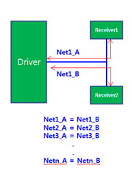
Figure 3.
- Base Length: Assign a reference pattern length.
- Start Component: Assign start component in case of multi-load system.
- Tolerance: Assign tolerance criteria, value/ratio.
- Value: Assign an allowable pattern length tolerance number, value/ratio.
- Via Existence: Select Via number check criteria.
- Not Check: Do not check via quantity
- Min: Check if via quantity is smaller than specific value
- Max: Check if via quantity is larger than specific value
- Via Qty: Assign reference Via quantity.
- Width: Option for width check
- Not Check: Do not check pattern width
- Check: Check if pattern width of each net is different.
- Include Via Length: DFE will include via length for calculating trace length.
The common clock interface method sends data sync to the driver’s own clock and receives data sync to the receiver’s own clock.
Parallel Bus
- Personal Computer Interface of PCI bus
- SCSI or Small Computer Systems Interface bus
- Compact PCI bus
- VME bus used in instrumentation
- Rambus interface
Serial Bus Examples
- LVDS
- Low Voltage Differential Signaling first devised to allow data transfer from laptop mother boards to flat panel displays.
- Fiber Channel
- A differential signaling protocol used to connect disc drive arrays together. Data rates as high as 1 gigabit per second is possible.
- Infiniband
- A full duplex differential signaling protocol intended to replace the
PCI bus in PCs and servers. Data rates as high as 2.5 gigabits per
second are possible.
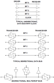
Figure 4.
Design Considerations for Buses
In parallel BUS, several data bits are sent from a source to you all at once. On arrival, the data is clocked into registers or other circuits that will operate on it. Clearly, layout must be done in such a way that all the bits arrive at the same time.
This means that routing pattern matching (length, width and via usage) will be required during PCB layout. The precision with which matching must be done is directly related to the data rate. The slower the data rate, the more time there is to wait for all bits to arrive allowing more length mismatch between bits in the bus. The faster the data rate, the smaller the time available to wait for bits to arrive resulting in a smaller budget for length mismatch among members of the bus.
Parallel buses have a limited data rate at which they can be reliably run. In most cases this is 225 megabits per second per line. When higher data transfer rates are needed, more lines are placed in parallel. When bus widths reach 128 lines, the noise transients associated with all lines switching from zero to one or one to zero can limit the length of the bus to an unusable dimension.
In addition to managing routing pattern to ensure timing is preserved among members of a bus, the designer must ensure that proper terminations are used to match drivers and loads to the lines and ensure that loads are spaced such that their loading does not degrade signals excessively.