Connected Circuit
This rule checks for the validity of circuit usage and whether the routing length and clearance from driver pins are within the specified distance.
- Item: Input item name.
- Net: Select a net group that needs a rectification filter circuit.
- Filter Circuit: Select a rectification filter circuit.
- Circuit AND/OR: If filter components are more than one, use this option.
- OR: If one of the filter components is located within specific distance, it passes.
- AND: Check if all selected filter components are located within specific distance.
- Start Comp: Select a component from which the circuit starts.
- Check Value: Assign distance value to which a rectification filter component
must be located from the staring component. This rule check reports the
following messages:
- No Filter: when there is no rectification component in target nets.
- No Start Comp: when there is no starting component in target nets.
- Distance Fail: when there is a rectification component in target net, but it violates the distance rule. In this case, it also reports the reference distance and measured distance.
Rectification circuit (or filter circuit) is a circuit to pass necessary frequencies but blocks or eliminates unnecessary frequencies. The purpose of using this filter is to get stability of signal. So, for important signal, it is necessary to check whether those nets have proper types of filter. In fact, it is very difficult to improper usage of filters without an aid of tools like PollEx DFE.
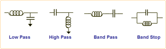
Figure 1.
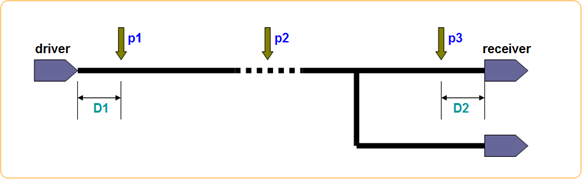
Figure 2.
Locations of p1, p2 and p3 are decided depending on the circuit characteristics and environment. Between p1 and p3, it is necessary to define maximum distance.