BUS (T-Topology)
T-Topology is commonly used for DDR memory. Using T-Topology, you can control skew and impedance efficiently.
This type of design should be ensuring that all the branches in the path are
carefully balanced, so they track each other effectively as voltage and temperature
variation occur over time. Thus:
- Make branch lengths the same to make equal transmission speed (delay).
- Make pattern widths the same to match impedances.
This DFE item checks routing length and width symmetry of each branch.
- Net: Select a target net group.
- Start Component: Select Start Component. If field is blank, the part with the highest number of pins is automatically targeted.
- Branch Length Check: DFE checks the length and symmetry of each
branch.
- Branch Length Symmetry Check: Check the branch length difference
between same order branches. Branch numbers are numbered from the
Start Component.
- B1_1 = B1_2
- B2_1 = B2_2 = B2_3 = B2_4
- B3_1 = B3_2 = B3_3 = B3_4 = B3_5 = B3_6 = B3_7 = B3_8
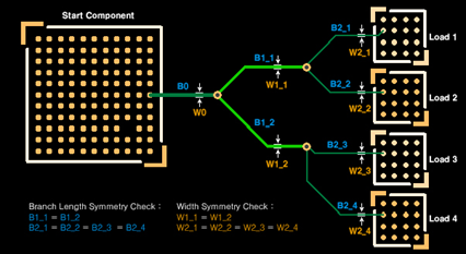
Figure 1. T-topology
- Tolerance: Assign tolerance criteria (value/ratio) and amount.
- Branch Length Check: Check branch length of all branches. Branch numbers are numbered from the Start Component.
- Max Branch Length: Define the required maximum branch length of each branch. The default branch stage is four. In case of less than four stage topology, leave remains as Zero.If branch value is Zero, DFE skips testing that branch.
- Tolerance: Assign tolerance criteria (value/ratio) and amount.
- Branch Length Symmetry Check: Check the branch length difference
between same order branches. Branch numbers are numbered from the
Start Component.
- Termination Length: DFE checks the branch length of termination component. Assign required maximum branch length of termination component.
- Terminator: Select termination component group.
- Layer Number: Define layer number. If you do not enter any specific value, the DFE gets the layer number from PCB property by default.
- Width Check: DFE checks the width and symmetry of each branch.
- Width Symmetry Check: Check the branch width difference between same
order branches. Branch numbers are numbered from the Start Component.
- W1_1 = W1_2
- W2_1 = W2_2 = W2_3 = W2_4
- W3_1 = W3_2 = W3_3 = W3_4 = W3_5 = W3_6 = W3_7 = W3_8
Figure 2. T-topology
- Tolerance: Assign tolerance criteria (value/ratio) and amount.
- Width Check: Check branch width of all branches. Branch numbers are numbered from the Start Component.
- Branch Width: Define required branch width of each branch. You can assign a different width value for different layers. The default branch stage is four. In case of less than four stage topology, leave remains as Zero.
- If width value is Zero, DFE skips testing that branch.
- Use longest segment width: The DFE uses the longest branch’s width by default. (per layer) You do not need to fill the width table.
- Tolerance: Assign tolerance criteria(value/ratio) and amount.
- Width Symmetry Check: Check the branch width difference between same
order branches. Branch numbers are numbered from the Start Component.
- Component Keep IN/OUT: Define test region. For example, you can test inside
or outside the breakout region of CPU with different test
values.
- Component Group: Select the required component group which is used for defining the test region.
- Region: Define the required test region.
- IN: Test inside of the breakout region of target component.
- OUT: Test outside of the breakout region of target component.
- Range (COC+distance): Enter the distance value to define breakout range. The COC (Component Overlap Check) plus this distance value is considered the test range.
- Target Layer: Select the required test layer.
- All Layer: Test all layers.
- Component Place Layer: Test only component placement layer.