Net Isolation
This item checks net connection between start pins to end pins.
The high-speed design open requires net isolation in order to reduce noise coupling which can lead to system malfunction. For example, the power sensing signal should be isolated from the high speed signal or other noisy power nets and low impedance connection is required.
This item checks net connection between start pins to end pins. They should be
connected directly from each start pin to each end pin and keep isolation. The
connections between start pins are not allowed.
- Item Name: Input item name.
- Type: Define net assign method.
- Pin: Target net is defined by specifying start pin and end pin. The net connected between start pin and end pin is considered as a target net.
- Net: Target net is defined by specifying net group, start component and end component. The net which is connected between start component and end component is considered as a target net.
- Pin-Comp: Target net is defined by specifying net group, start pin and end component. The net which is connected between start pin and end component is considered as a target net.
- Start: Define start point of target net. If you double click the empty
column, the different dialog will display according to selected Type option.
- If you selected Type as Pin or Pin-Comp: double click the
Start column. The Net Isolate
Check Option dialog displays.
- Click the required start component group from the Component Group List.
- Click the arrow button. All components that belong to that group are listed.
- Assign the required start pin number into Select Pins column. In case of multiple pins, the separator is space.
- Click OK to close this dialog.
- If you selected Type option as Net: double-click the Start column. The Select Object Group dialog displays. You can select required start component groups with this dialog.
- If you selected Type as Pin or Pin-Comp: double click the
Start column. The Net Isolate
Check Option dialog displays.
- End: Define end point of target net. If you double-click the empty column,
the different dialog displays according to selected Type option.
- If you selected Type as Pin: double-click the
End column. The Net Isolate
Check Option dialog displays.
- Click the required end component group from the Component Group List.
- Click the arrow. All components that belong to that group are listed.
- Assign required end pin number into Select Pins column. In case of multiple pins, the separator is space.
- Click OK to close this dialog.
- If you select Type option as Net or Pin-Comp: double-click the End column. The Select Object Group dialog displays. You can select the required end component groups.
- If you selected Type as Pin: double-click the
End column. The Net Isolate
Check Option dialog displays.
- End Comp Search Distance: Assign the distance limit of end Component. The components within this range (from Start Component) limit will be considered as End Component.
- Net: Select target net group. This option is valid only when you select Type as Net or Pin-Comp.
- Start Connection: Connections between start pins are allowed, otherwise start pins should be isolated from each other.
- End Type: Define the end point test condition.
- Don’t care: Check between start pin and end pin only. Do not check
beyond end pin.
Figure 1. 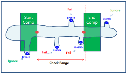
- M-GND: Check between start pin and end pin. Check if end point is
directly connected to M-GND.
Figure 2. 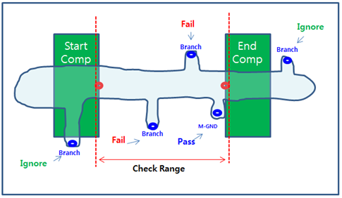
- Branch: Check between start pin and end pin, and check beyond start
pin and end pin. If branch exist beyond start pin, it reports fail.
If branch exist beyond end pin, ignore it.
Figure 3. 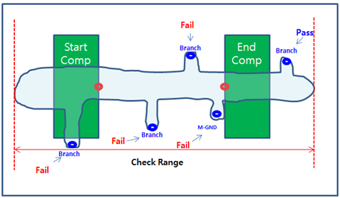
- Don’t care: Check between start pin and end pin only. Do not check
beyond end pin.
- M-GND Count: Specify the number of main ground layer. The DFE assigns main ground layer by ground copper area in order.
- Width: Assign required width of target net.
- Measure Type: Select one of the following types to be used for width checking.
- Min/Max/Range
- Tolerance (%): Tolerance (%) to measure an allowable target net width.
- Comments: Comments field. It is just commenting but the excel report include this field.
- Test Options: It provides an option to check for Net Isolation in terms of
M-plane connection, both-end branching restrictions, and main route width,
along with additional features like allowing the combination of start pins
and extending the main route range.
Figure 4. 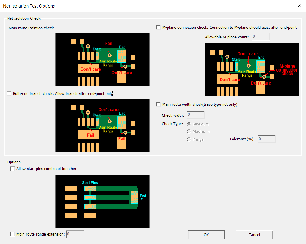
- Net Isolation check
- M-plane connection check: Connection to M-plane should exist after end-point
- Both-end branch check: Allow branch after end-point only
- Main route width check: trace type net only
- additional options
- Allow start pins combined together
- Main route range extension
- Net Isolation check