Passive Device Stability
This item checks whether the filter installed in the IO terminal is well designed with low impedance.
To prevent problems such as EMI or ESD occurring at the port end of the product,
normally a filter is installed at the IO end. In order to completely prevent this
problem, a lot of consideration is required when designing a filter.
- Item: Input item name.
- Net Group: Set IO net group to which filter is connected.
- Start Component: Set IO component group filter that should be used.
- Passive Component: Set filter component group.
- Test Option
- A Side Check (Trace Only): Option for connection path test between
filter and component.
Figure 1. 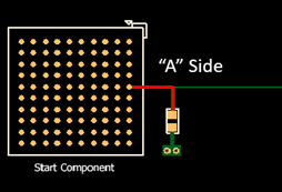
- Check minimum trace width: DFE checks the minimum width of trace between Filter and Component.
- Check maximum distance: DFE checks the maximum distance between Filter and Component.
- Check maximum trace length: DFE checks the maximum trace length between Filter and Component.
- B Side Check (Trace Only): Option for connection path test between
filter and ground.
Figure 2. 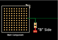
- Minimum polygon size to be considered as stable PWR/GND: Defines the minimum size of a polygon that can be considered a stable ground. When performing the following tests, DFE calculates and checks the total length of the entire path connected from the filter to the stable ground.
- Check trace length to stable PWR/GND: DFE checks the path
between Filter and stable ground.
Maximum total trace length: DFE checks the maximum trace length between Filter and stable ground.
Maximum total segment length/width ratio: DFE checks the maximum trace length/width ratio between Filter and stable ground.
- Considered as pass if one good path to stable PWR/GND exist: If there are multiple connection paths between Filter and Stable Ground, if even one path satisfies the criteria, the whole is judged as a pass.
- A Side Check (Trace Only): Option for connection path test between
filter and component.
- Test Options: Common test option
- Passive Component PAD should be connected to Net directly: The DFE
checks whether the PAD of the filter is placed directly onto the
main net.
- End Component: The DFE determines that the path where the Start Component and this End Component are connected is the main route.
- Passive Component should be placed on the same layer with Component: DFE checks whether the filter is placed on the same side as the start component.
- Include VIA length: The length of VIA is also included when
calculating net length.
- VIA Length Compensation: Since the inductance of VIA is different from the inductance of trace, this factor is used when calculating the effective length of VIA.
- Passive Component PAD should be connected to Net directly: The DFE
checks whether the PAD of the filter is placed directly onto the
main net.