Manage Subsystem Configurations
Group unique subsystems together into subsystem sets and organize both subsystems and subsystem sets into configurations.
The typical model assembly workflow is to set each subsystem up as an include file. Each configuration of subsystems is then managed through a separate header deck referencing the appropriate include files. This is an efficient way of building a model since updates can be performed per subsystem rather than per system model. However, this requires multiple header decks to be updated, strict management of ID ranges for each include, as well as control over the connectivity between includes.
Subsystems support and enhance this workflow since each subsystem can be written out as an include file. Additionally, all subsystems and subsystem configurations are stored in a single .hm file. When a particular subsystem is updated, multiple header decks can be written out from a single file using configurations rather than editing multiple header decks.
ID management is covered through the ID Manager. Connectivity between subsystems is managed through Subsystem Attachments and Connectors. This ensures that connectivity is maintained to the other subsystems even if one subsystem is worked on independently.
Common Subsystem
If you do not explicitly assign a subsystem to any specific configuration, it is treated as a common subsystem. It will be automatically included in all configurations, without needing to assign it to each configuration individually.
Activation of a configuration keep active the common subsystems, the unique subsystems in that configuration, and deactivate any unique subsystems that are in a different configuration.
Configuration View
- Subsystem configuration view in the Subsystem Browser.
- Subsystem configuration table view.
- Subsystem Configuration View in the Subsystem Browser
- The standard view for creating and managing subsystem configurations. To
access it from the Subsystem Browser, select the
Subsystem Include View icon,
 , followed by the Subsystem
Configuration View icon,
, followed by the Subsystem
Configuration View icon,  .
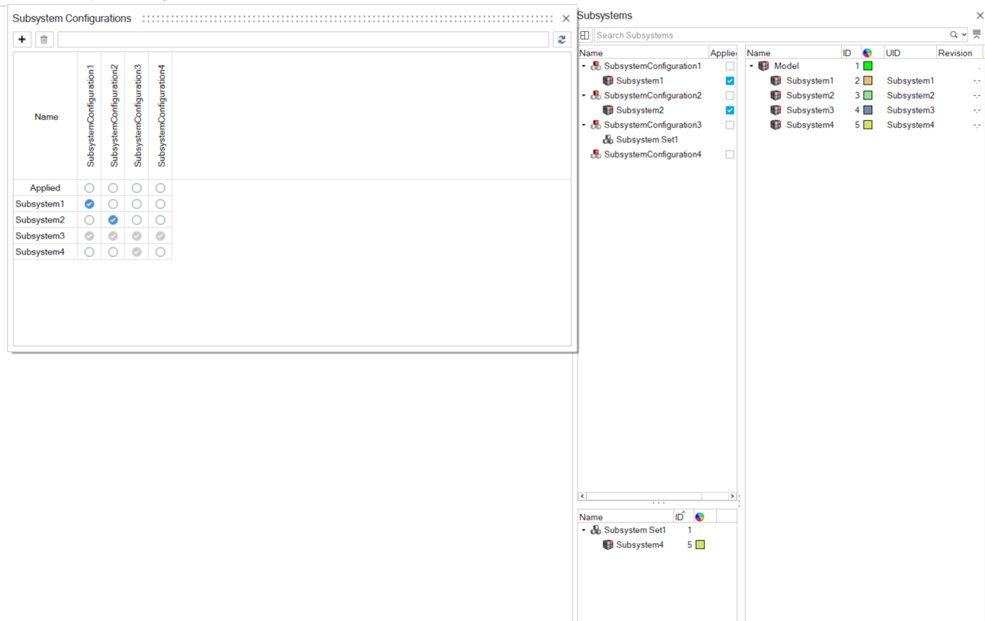
.Figure 3. Subsystem Configuration View 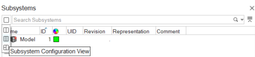
- Subsystem Configuration Table View
- The table view provides a clear overview of the included and excluded subsystems within a configuration. This makes creating and managing configurations easier.
- To access this view, from the Assembly ribbon, click the Subsystem
tool's satellite icon.
Figure 4. Subsystem Browser Tool and Satellite Icon 
- Applied Configuration
- The first row in the table represents the applied configuration. This row indicates which configuration is currently active and which one will be exported.
- Icon Legend
- The table uses icons to show the relationship between
subsystems and configurations:
Option Description Blue checkmark  - Direct
connection
- Direct
connectionThe subsystem is explicitly included in the configuration. Empty circle  - No connection
The subsystem is not linked to a configuration and will be inactive. Grayed-out checkmark  - Indirect connection
 The subsystem is included indirectly to the configuration because: - The configuration references another configuration.
- The configuration contains a subsystem set.
- The subsystem is common.
- The subsystem is an associated connector subsystem.
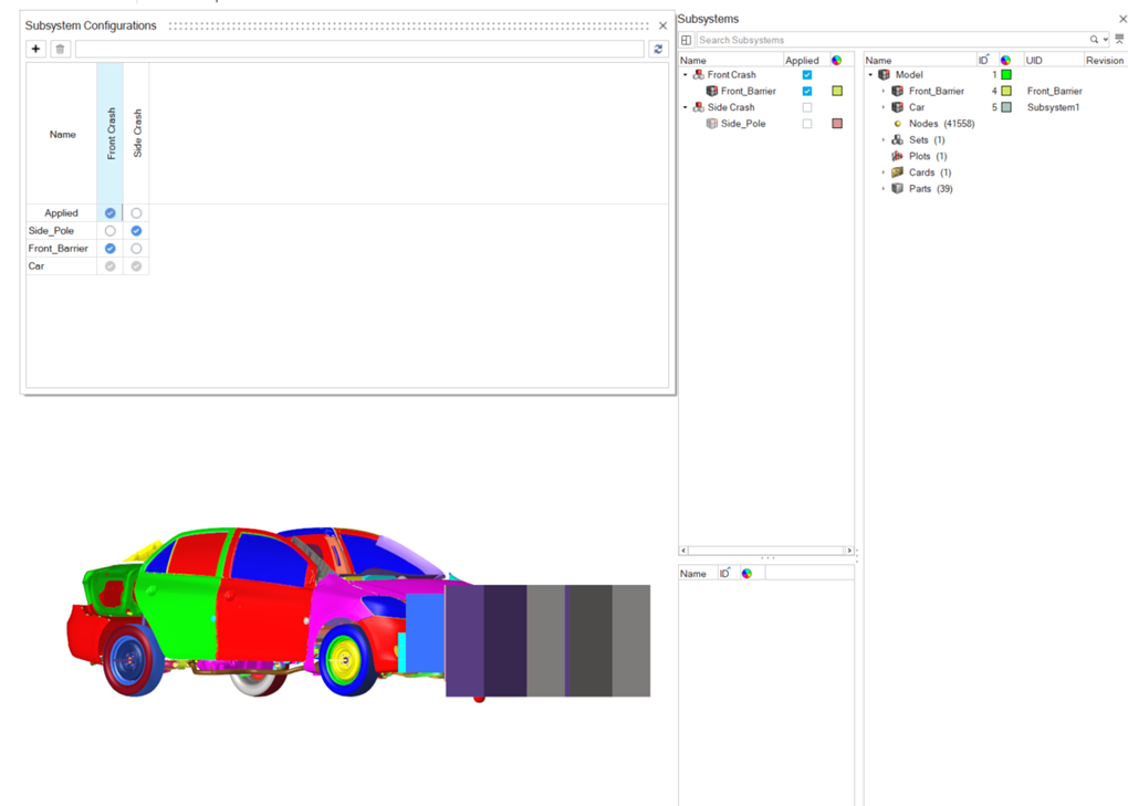
Figure 5. Subsystem Configuration Table View