Create Midmesh
Use the Midmesh: Automatic tool to automatically generate a mesh at the midplane location, directly from the input geometry (components, elements, solids or surfaces), without first creating a midsurface. This saves significant time over the traditional midsurface-based approach.
-
From the 2D ribbon, click the tool.
Figure 1. 
- Optional:
On the guide bar, click
 to define midmesh
options.
to define midmesh
options.
-
Select geometry.
Use the drop down menu on the guide bar selector to choose components, elements, solids, or surfaces as the source geometry type.
- Edit the extraction size value in the microdialog.
- Click Midmesh in either the microdialog or the guide bar.
Options for Creating Midmesh
Access the following options by clicking ![]() on the
Midmesh: Automatic tool guide bar.
on the
Midmesh: Automatic tool guide bar.
- Edit criteria
- Set the minimum size and target element size settings in the criteria file to control the resulting midmesh via the Criteria File Editor.
- Extraction size
- The midmesh extraction element size. By default this is taken as the target element size from the criteria file. This can be set smaller than the target size, though that is not recommended unless there are problems extracting at the target size.
- Minimum size
- Minimum element size allowed in the finalized mesh. This in combination
with the ‘suppress proximity edges factor’ and 'combine non-manifold
edges factor’ can ensure that the output mesh is ready for rebuild with
the same criteria.
Can only be modified in the Criteria File Editor.
- Element Type
- Select the output element type.
- Method
- Select the method of midmesh extraction.
- Casting
- Generate midmesh optimized for casting parts. The casting method handles midmesh on complex, freeform surfaces and variations in thickness.
- Extrusion
- Perform midmesh extraction on extrusion parts. The extrusion method handles midmesh on linear and consistent cross-sectional profiles.
- Mask input entities
- Hide input midmeshed entities in the modeling window upon exiting the context.
- Destination component
- Select which component newly created midmeshes are placed in.
- Ignore flat edges
- Do not imprint flat edges from the input geometry onto the
midmesh.
Figure 2. Option Off 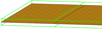
Figure 3. Option On 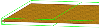
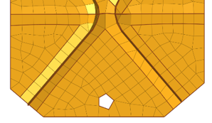
- Flatten connections
- Aligns/flattens the midmesh at ribs/connections.
Figure 4. Option Off 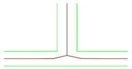
Figure 5. Option On 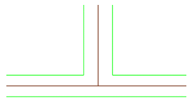
- Step offset mode
- This option allows finer control of how stepped geometry (one side continuous surface, and opposite side steps) is captured. This option is valid only when flatten connections is enabled. Values can be:
- Middle of thinnest plate – All steps that share a
common base are moved to the middle of the thinnest step.
Figure 6. 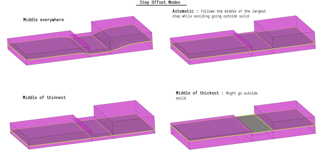
- Suppress proximity edges factor
- The minimum size factor for removing edges within proximity. Edges
closer than this factor times minimum size will be
suppressed.
Figure 7. Option Off 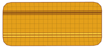
Figure 8. Option On 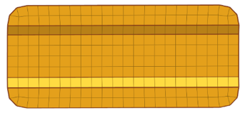
- Fillet treatment factor
- The minimum size factor to remove small fillets. Fillets smaller than
this factor times minimum size will be removed.
Figure 9. Option Off 
Figure 10. Option On 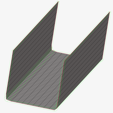
- Combine non-manifold edges factor
- The minimum size factor for joining non-manifold edges. Non-manifold
edges closer than this factor times minimum size will be
combined.
Figure 11. Option Off 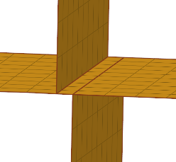
Figure 12. Option On 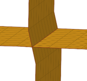
- Defeature ribs width factor
- The minimum size factor for removing small ribs. Ribs closer than this factor times minimum size will be suppressed. Default is 0.9.
- Defeature openings with width <
- The minimum size factor for removing small holes and
openings.
Figure 13. Option Off 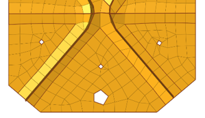
Figure 14. Option On