Align Midmesh
Use the Align tool to correct and improve midmesh quality by aligning selected midmesh surfaces or edges to specified guide geometry.
-
From the 2D ribbon, click the tool.
Figure 1. 
- Optional:
On the guide bar, click
 to define alignment
options.
to define alignment
options.
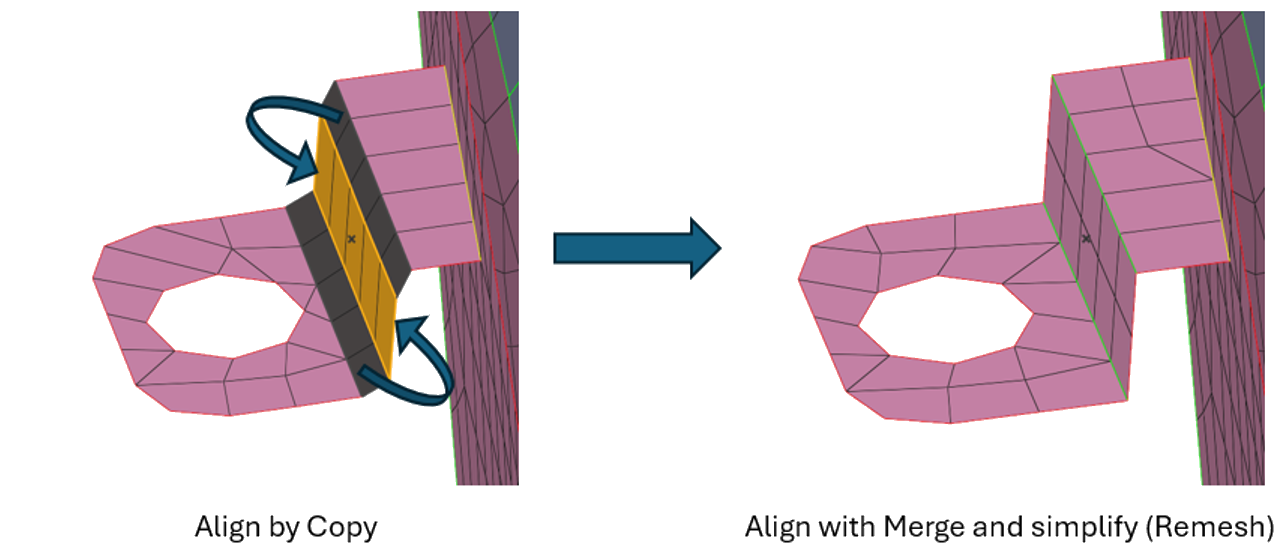
- Merge and simplify
- Remove shared edges between adjacent midmesh surfaces and merge them into a continuous surface. This reduces unnecessary edge divisions, enhances mesh quality, and simplifies the model.
- Remesh
- Remesh the midmesh surfaces after alignment, adjusting element size
and distribution to improve uniformity and preserve quality.
Figure 2. 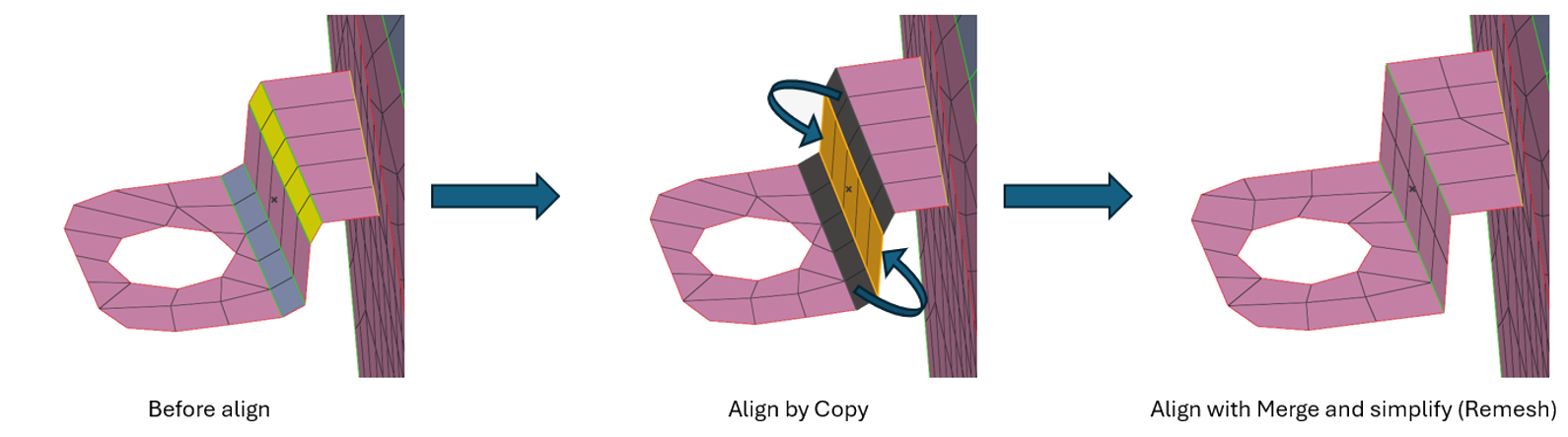
-
Align midmesh.
To align Do this Middle Align midmesh surface(s) between Guide A and Guide B geometry surface sets. - Use the Surface selector to select the midmesh surface(s) to align.
- Use the Guide A selector to choose the first guide surface(s).
- Use the Guide B selector to choose the second guide surface(s).
- Click Align to perform the operation.
Note: Guide surfaces are auto-populated based on the stored attributes of the selected midmesh surfaces.Figure 3. 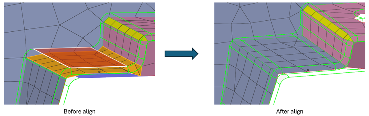
Edge Align Align midmesh edge(s) under geometry line(s) or extend to target geometry surface(s). - Use the Lines selector to choose the midmesh edge(s) to align.
- Use the Guide A selector to choose the
geometry edge(s) beneath which the selected midmesh edge(s) will
be aligned.Tip: You can use the Guide A selector to choose the geometry surface(s) to which the selected midmesh edge(s) will be extended.
- Click Align to perform the operation.
Figure 4. 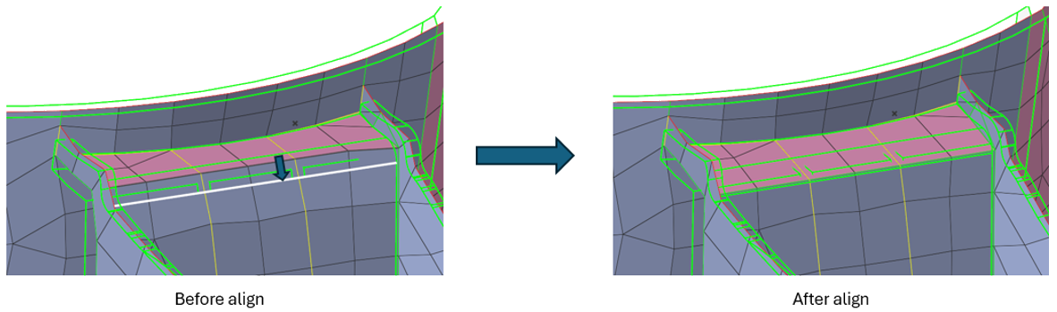
Plane Align midmesh surface(s) to the specified plane. - Use the Surface selector to select the midmesh surface(s) to align.
- Use the Plane selector to define the target plane using the manipulator.
- Click Align to perform the operation.
Figure 5. 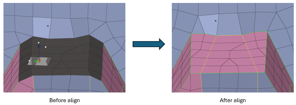
Cylinder Align midmesh surface(s) to the specified cylinder. - Use the Surface selector to select the midmesh surface(s) to align.
- Use the Guide selector to define the
target cylinder using geometry surface(s).Tip: You can use the Locations selector to pick three points for defining the cylinder.
- Click Align to perform the operation.
Figure 6. 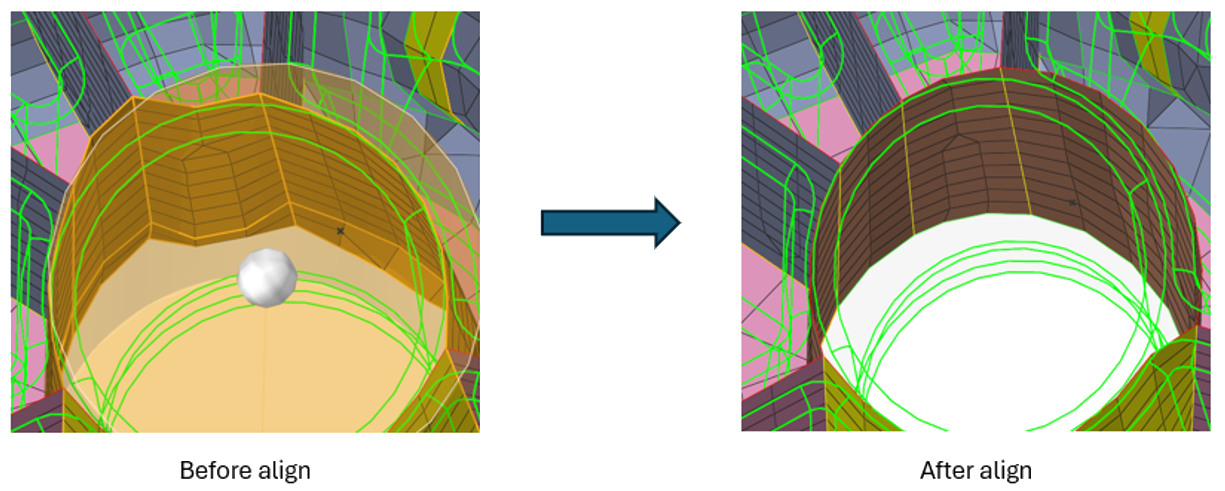
Offset Align midmesh surface(s) using an offset value from geometry surface(s). - Use the Surface selector to select the midmesh surface(s) to align.
- Use the Guide selector to select the geometry surface(s) from which the selected midmesh surface(s) will be offset.
- In the microdialog, specify the offset value.
- Click Align to perform the operation.
Figure 7. 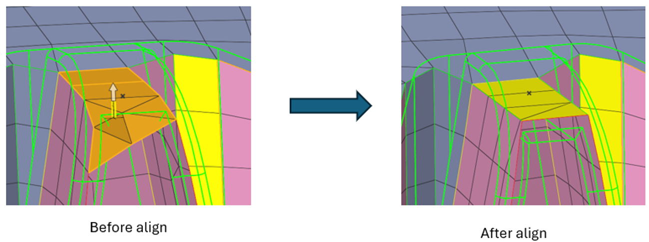
Fuse Fuse two sets of midmesh edges together. - Use the Edge A selector to select the first set of midmesh edge(s) to be fused.
- Use the Edge B selector to select the second set of midmesh edge(s) to be fused.
- Click Align to perform the operation.
Figure 8. 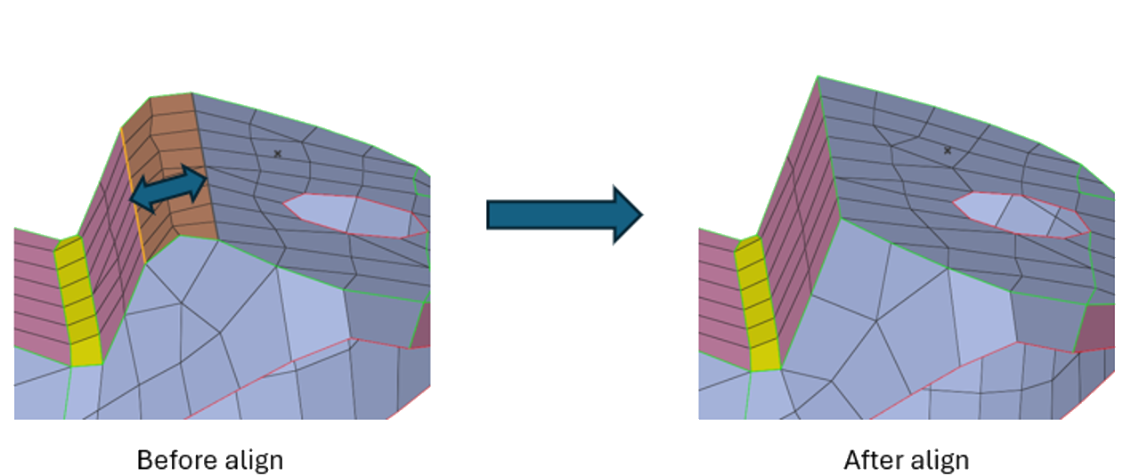
Copy Align midmesh surface(s) using attributes from another midmesh surface. - Use the Surface selector to select the midmesh surface(s) to align.
- Use the Guide selector to select the midmesh surface(s) whose attributes will be applied.
- Click Align to perform the operation.
Figure 9.