Element Configurations
Each element has an associated element configuration. An element configuration tells HyperMesh how to draw, store, and work with the element.
Bar Elements
1D elements created in a space between two or three nodes of a model where beam properties are desired.
The nodes are related to each other based on the properties of the bar or beam element connecting them. Properties associated with bar elements include vector orientation, offset vectors that end at A and B, or at A, B, and C, and pin flags to tell it what degree of freedom should carry through the beam.
Bar elements are displayed as a line between two nodes with BAR2 or BAR3 written at the centroid of the element.
- Bar2
- Configuration 60 - 1D (1st order) elements with 2 nodes used to model axial, bending, and torsion behavior. Bar2 elements have a property reference, an orientation vector, offset vectors and ends A and B, and pin flags at ends A and B.
- Bar3
- Configuration 63 - 1D (2nd order) elements with 3 nodes used to model axial, bending, and torsion behavior. Bar3 elements have a property reference, an orientation vector, offset vectors and ends A and B, and pin flags at ends A and B.
Gap Elements
Configuration 70 - 1D elements created in a space between two nodes, or between a node and an element, of a model where contact may occur.
Create a gap element when you want to impose a nonlinear constraint on a model; this constraint will limit the amount of movement possible during analysis.
Gap elements have a property reference and an orientation vector.
Gap elements are displayed as a line between two nodes with GAP written at the centroid of the element.
Gap elements can translate to CGAP or CGAPG elements in OptiStruct, CGAP element in Nastran or *GAP option in Abaqus.
Hex Elements
3D hexahedra elements.
- Hex8
- Configuration 208 - 3D (1st order) hexahedra elements with 8 nodes.
Figure 1. 
- Hex20
- Configuration 220 - 3D (2nd order) hexahedra elements with 20 nodes.
Figure 2. Element Configuration 220, 20-Noded Hexa 
Joint Elements
Configuration 22 - 1D elements with 2, 4, or 6 nodes which have a property and orientation systems or nodes.
Joint element is a definition of a connection between two rigid bodies. Joint elements store a property and orientation information.
Joint elements are displayed with lines between the appropriate nodes and the letter J between nodes 1 and 3 of the element.
| Type | Type Name | Number of Nodes | Orientation | Solver Interface |
|---|---|---|---|---|
| 1 | Spherical joint | 2 |
|
|
| 2 | Revolute joint | 4 |
|
LS-DYNA |
| 3 | Cylindrical joint | 4 |
|
LS-DYNA |
| 4 | Planar joint | 4 |
|
LS-DYNA |
| 5 | Universal joint | 4 |
|
LS-DYNA |
| 6 | Translational joint | 6 |
|
LS-DYNA |
| 7 | Locking joint | 6 |
|
LS-DYNA |
| 8 | Ball joint | 2 | None | OptiStruct |
| 9 | Fixed joint | 2 | None | OptiStruct |
| 10 | Revolute joint | 2 |
|
OptiStruct |
| 11 | Translational1 joint | 2 |
|
OptiStruct |
| 12 | Cylindercal 1 joint | 2 |
|
OptiStruct |
| 13 | Universal joint | 2 |
|
OptiStruct |
| 14 | Constant_velocity joint | 2 |
|
OptiStruct |
| 15 | Planar joint | 2 |
|
OptiStruct |
| 16 | Inline joint | 2 |
|
OptiStruct |
| 17 | Perpendicular joint | 2 |
|
OptiStruct |
| 18 | Parallel axes joint | 2 |
|
OptiStruct |
| 19 | Inplane joint | 2 |
|
OptiStruct |
| 20 | Orient joint | 2 |
|
OptiStruct |
| 21 | Point_to_curve joint | 2 |
|
OptiStruct |
| 22 | Curve_to_curve joint | 2 |
|
OptiStruct |
| 23 | Point_to_deformable_curve joint | 2 |
|
OptiStruct |
| 24 | Point_to_deformable_surface joint | 2 |
|
OptiStruct |
| 25 | Translational_2N joint | 2 |
|
PAM-CRASH |
| 26 | Revolute_2N joint | 2 |
|
PAM-CRASH |
| 27 | Cylindrical_2N joint | 2 |
|
PAM-CRASH |
| 28 | Universal_2N joint | 2 |
|
PAM-CRASH |
| 29 | Flexion-Torsion joint | 2 |
|
PAM-CRASH |
| 30 | Planar_2N joint | 2 |
|
PAM-CRASH |
| 31 | General joint | 2 |
|
PAM-CRASH |
| 32 | Bracket joint | 2 |
|
PAM-CRASH |
| 33 | Free joint | 2 |
|
PAM-CRASH |
Mass Elements
Configuration 1 - 0D elements with a single node that allow you to assign concentrated mass to the model in order to represent a physical part that may not be modeled with another FE idealization.
Mass elements are displayed as a dot with the letter M written at the centroid of the element.
Main Elements
Main interface elements.
- Main3
- Configuration 123 - Main interface elements with 3 nodes. (Must be Type 1).
- Main4
- Configuration 124 - Main4 elements are main interface elements with 4 nodes. (Must be Type 1).
Penta Elements
3D triangular prism pentahedra elements.
- Penta6
- Configuration 206 - 3D (1st order) triangular prism pentahedra elements with 6
nodes.
Figure 3. Element Configuration 206, 6-Noded Penta 
- Penta15
- Configuration 215 - 3D (2nd order) triangular prism pentahedra elements with 15
nodes.
Figure 4. Element Configuration 215, 15-Noded Penta 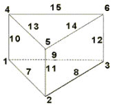
Plot Elements
Configuration 2 - 1D elements with 2 nodes used for display purposes.
Plot elements are displayed as a line between two nodes.
Pyramid Elements
3D pyramid pentahedra elements.
- Pyramid5
- Configuration 205 - 3D (1st order) pyramid pentahedra elements with 5 nodes.
Figure 5. Element Configuration 205, 5-Noded Pyramid 
- Pyramid13
- Configuration 213 - 3D (2nd order) pyramid pentahedra elements with 5 nodes.
Figure 6. Element Configuration 213, 13-Noded Pyramid 
Quad Elements
2D quadrilateral elements.
- Quad4
- Configuration 104 - 2D (1st order) quadrilateral elements with 4 nodes.
Figure 7. Element Configuration 104, 4-Noded Quad 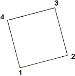
- Quad8
- Configuration 108 - 2D (2nd order) quadrilateral elements with 8 nodes.
Figure 8. Element Configuration 108, 8-Noded Quad 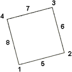
RBE3 Elements
Configuration 56 - Rigid elements with one dependent node and variable independent nodes typically used to define the motion at the dependent node as a weighted average of the motions at the independent nodes.
Both the dependent node and independent nodes contain a coefficient (weighting factor) and user-defined degrees of freedom. The dependent degrees of freedom and weighting factors can be specified or automatically calculated based on the geometry.
RBE3 elements are displayed as lines between the dependent node and the independent node(s) with RBE3 displayed at the dependent node of the element.
Rigid Elements
Configuration 5 - Rigid 1D elements with 2 nodes used to model rigid connections.
Rigid elements are displayed as a line between two nodes with the letter R written at the centroid of the element.
Rigids can translate to RBE2 in Nastran or *MPC in Abaqus.
Rigidlink Elements
Configuration 55 - Rigid elements with one independent node and variable dependent nodes typically used to model rigid bodies.
Rigidlink elements have user-defined degrees of freedom which apply to all dependent nodes.
Rigidlink elements are displayed as lines between the independent node and the dependent node(s) with RL displayed at the independent node of the element.
Rod Elements
Configuration 61 - 1D elements with 2 nodes used to model axial behavior only.
The two nodes are related to each other based on the properties of the rod element connecting them. Rod elements have property pointers.
Rod elements are displayed as a line between two nodes with ROD written at the centroid of the element.
Rods can translate to CTUBES in Nastran or a C1D2 element in Abaqus.
Secondary Elements
Secondary interface elements.
- Secondary1
- Configuration 135 - Secondary interface elements with 1 node. (Must be Type 1).
- Secondary3
- Configuration 133 - Secondary interface elements with 3 node. (Must be Type 1).
- Secondary4
- Configuration 134 - Secondary interface elements with 1 node. (Must be Type 1).
Spring Elements
Configuration 21 - 1D elements used to model spring connections.
Spring elements have user-defined degrees of freedom, an orientation vector, and a property reference.
Spring elements are displayed as a line between two nodes with the letter K written at the centroid of the element.
- Spring
- 1D elements with 2 nodes used to model spring connections.
- Spring2N
- 1D elements with 2 nodes used to model spring connections.
- Spring3N
- 1D elements with 3 nodes used to model spring connections.
- Spring4N
- 1D elements with 4 nodes used to model spring connections.
Springs can translate to CELAS2 in Nastran or *SPRING in Abaqus.
Tetra Elements
3D tetrahedra elements.
- Tetra4
- Configuration 204 - 3D (1st order) tetrahedra elements with 4 nodes.
Figure 9. Element Configuration 204, 4-Noded Tetra 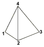
- Tetra10
- Configuration 210 - 3D (2nd order) tetrahedra elements with 10 nodes.
Figure 10. Element Configuration 210, 10-Noded Tetra 
Tria Elements
2D triangular elements.
- Tria3
- Configuration 103 - 2D (1st order) triangular elements with 3 nodes.
Figure 11. Element Configuration 103, 3-Noded Tria 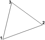
- Tria6
- Configuration 106 - 2D (2nd order) triangular elements with 6 nodes.
Figure 12. Element Configuration 106, 6-Noded Tria 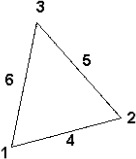
Weld Elements
Configuration 3 - Rigid 1D elements with 2 nodes used to model welded connections.
Weld elements are displayed as a line between two nodes with the letter W written at the centroid of the element.
Xelems
1D multi-strand elements.