Radio Coverage Solution
![]()
Introduction
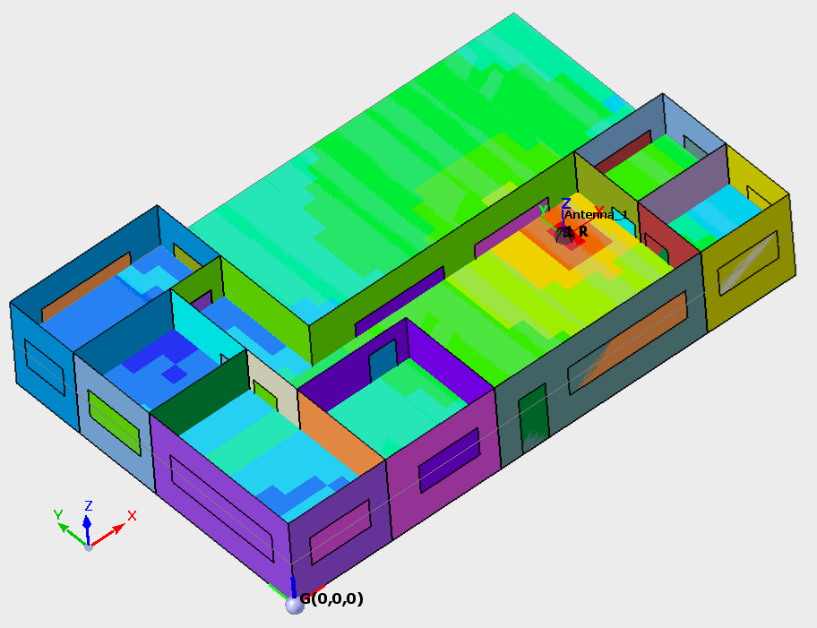
The Radio Coverage solution is used to predict the radio coverage inside a building as well as radio channel analysis for almost every standard (cellular including but not limited to 5G, LTE, Wi-Fi, broadcasting and TETRA).
Solution type
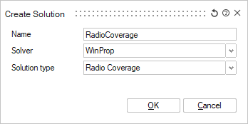
- Radio coveragePredict the radio coverage inside a building.
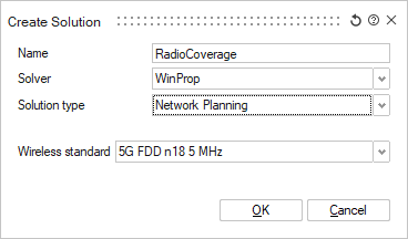
- Network planningPredict the radio channel analysis inside a building.
-
- Standard (all scenarios and models)
- The antenna pattern (both for Tx and Rx) can come from a Feko .ffe file (which contains polarization information but the standard option will only extract the total gain) or from other file formats such as .apa, .apb, or .pln and .msi files which do not contain polarization information. When this Standard option is used, the polarization information is defined when antenna patterns are assigned to individual transmitters. The selected polarization direction and cross-polarization level apply uniformly to all directions in the radiation pattern.
-
- Full (limited)
- Angle-dependent (direction-dependent) polarization information is obtained from the antenna pattern (both Tx and Rx) in the Feko .ffe or an .ffe file created in AMan. The .ffe file contains the polarimetric information (gain and polarization) where separate patterns for theta and phi polarization are included in the file. Due to the level of detail, this option can only be selected in conjunction with non-empirical prediction models that take the polarization accurately into account. These are standard ray tracing, intelligent ray tracing, and the multi-wall model with the use of Fresnel coefficients/ UTD for transmission, reflection and diffraction.
-
- Predefined
- Select a predefined wireless standard.
-
- MIMO Technology
- MIMO technology can be either disabled or enabled using two to
eight parallel streams.
Multiple-input and multiple-output (MIMO) technology is the use of multiple antennas at both the transmitter and receiver to improve communication performance. MIMO technology offers significant increases in data throughput and link range without additional bandwidth or transmit power. It achieves this by higher spectral efficiency (more bits per second per hertz of bandwidth) and link reliability or diversity (reduced fading). Because of these properties, MIMO is an important part of modern wireless communication standards such as WiMAX, HSPA+, 3GPP Long Term Evolution, 4G, and IEEE 802.11n (Wifi).
The MIMO antenna configuration can be used for spatial multiplexing. In this case a high rate signal is split into multiple lower rate streams and each stream is transmitted from a different transmit antenna in the same frequency channel. If these signals arrive at the receiver antenna array with sufficiently different spatial signatures, the receiver can separate these streams into (almost) parallel channels. Accordingly the spatial multiplexing by using MIMO antennas is a powerful technique for increasing channel capacity at higher signal-to-noise-and-interference ratios (SNIR). The maximum number of spatial streams is limited by the lesser in the number of antennas at the transmitter or receiver.
Typical MIMO schemes are MIMO 2x2 (that is two antennas each at both transmitter and receiver), and MIMO 4x4. In case of spatial multiplexing each MIMO antenna element transmits a separate MIMO data stream. The MIMO scheme 4x2 transmits the MIMO stream 1 from two antenna elements and the MIMO stream 2 from two other antenna elements, combining MIMO with a distributed antenna system (DAS). The receiver includes also two antenna elements (for separating the two different MIMO streams).
-
- Import wireless standard (.wst)
- Import a wireless standard. from a .wst file.
Workflow in SimLab:
- Define the sketch plane.
- Set the model units for the model.
- Use 2D sketches to define the building floor plan, doors, and windows. The
sketches are realized as single sheet bodies to create the building geometry.
- Create a 2D sketch of the floor plan.
- Create the floor using the sketch of the floor plan and realize as single sheet body.
- Create the walls of the building by extruding the floor plan.
- Create the ceiling of the building by duplicating the floor plan and then moving the ceiling to the correct height.
- Create doors and windows by creating a sketch where you want to
place a door or windows. Realize the sketches as single sheet
bodies.Note: Using the Sketch > Image Plane tool, you can import an image of the floor plan and draw over the background image.
- Adding material properties.
- Select the material from the database and make it available by pulling into the model.
- Apply the material properties to the floor, ceiling, doors, walls and windows.
- Create a radio coverage solution for the model (bodies).Note: Select one of the following solution types:
- Radio coverage
- Network planning
- Add an antenna to the model.
- Specify or import the air interface (only applicable to network planning).
- Define a prediction plane where the results are to be predicted when running the WinProp Solver.
- Specify the propagation model.
- Define the result requests.
- Solve the model.