Streamlines
![]()
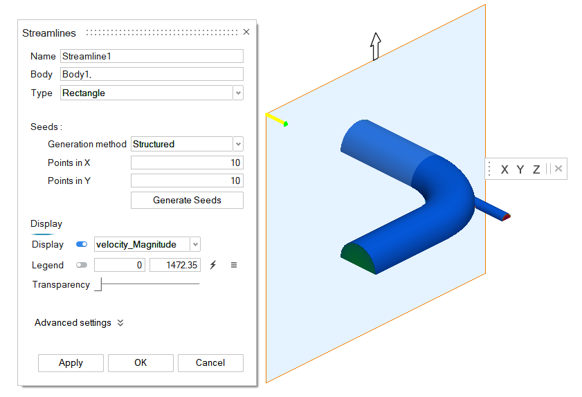
Use the Streamlines tools to create derived geometry streamlines which represent particle paths in a flow field. You must define seed points, vectors from which streamlines are computed as well as the integration direction.
From the post ribbon, click the Streamlines tool to create Rake or Rectangle streamlines.
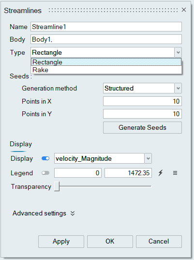
Type
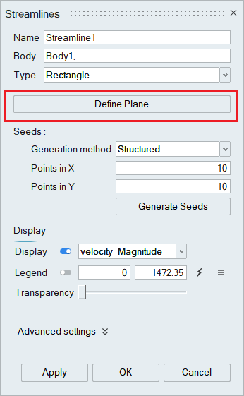
Rectangle
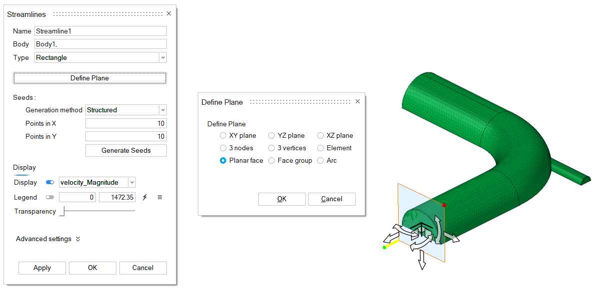
Click the Define plane option that turns OFF flow post display and updates SimLab geometry in UI and it also opens the Define plane dialog, having options to define a plane using SimLab Geometry. The seeds are generated on the plane defined.
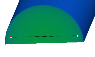
Rake
A rake is defined by two end points. Pick two points directly from the model in the graphics window as shown below.
Seeds
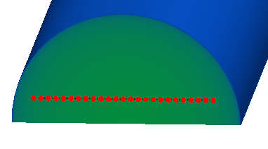
Seeds can be generated in a structured or random manner.
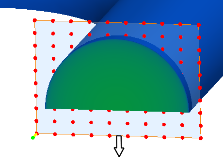
Specify the number of seeds to be positioned in a random or structured manner and click Generate seeds option to visualize the seed points location in UI as shown below.
Structured seed generation
Rake
Rectangle
Display
Options under display can be used to vary the contour data, legend location, adjust transparency of the streamlines.Advanced Settings
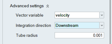
Advanced Settings opens the options, where you can change parameters which control how the streamlines are generated.
Vector variable: Select the vector from which the streamlines are computed.
Integration direction:
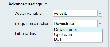
- Downstream - Integration is done following the velocity field direction.
- Upstream - Integration is done upstream, or opposite, to the velocity field direction.
- Both - Integration is done both downstream and upstream.
Tube radius:
This option can be used to vary the tube radius of the streamlines.
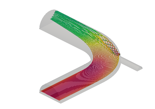
Click Apply or Ok to visualize the streamlines in the graphics window as shown below.
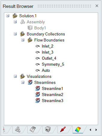
To edit the streamlines definition and display style, double-click on a streamline in the Result Browser.