Mesh Settings
![]()
Description
Mesh settings hold the ElectroFlo solver mesh parameters and it is used to view/modify the mesh parameters as required.
The solver mesh parameters are:
- Maximum first layer height in X, Y, Z - It is the maximum allowable element edge length of the first layer created from each keyplanes in X, Y, Z.
- Maximum mesh size in X, Y, Z - It is the maximum allowable element edge length in X, Y, Z.
- Grade factor - It is the ratio between adjacent element edges and this ratio should not exceed the specified value.
- Aspect ratio - It is the ratio between the longest element edge length by shortest element edge length of each hex element and this ratio should not exceed the specified value.
Create Mesh
EFlo mesh is the fine mesh based on mesh parameters and it is created from the bodies in solution. This option is used to create it.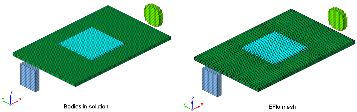
For "Thermal and Flow", "Thermal and Frozen Flow" simulations, the “Display air region” option will be shown in the “Mesh Settings” dialog, it is used to display the created air body and it gets assigned with default fluid material in "Solution Parameters | Advanced Options".
Note:
- By using an environmental variable "SIMLAB_EFLOMESH_LINES" as TURE, EFlo mesh bodies are created as wire body with mesh lines (element edges) instead of solid body with hex elements.
- If an environmental variable "SIMLAB_RETAIN_GD" is set to TRUE, the “Display air region” option will not be available in the dialog and the created mesh will not be added to the solution.