Align
![]()
Description
A CAD model has features such as planes, cylinders and more. The meshing process can move nodes and not follow the feature shape. For example, nodes on a planar surface, in some cases, need not be on the plane. This can happen due to the presence of sliver surface next to the plane surface. In this case you might want to move the nodes on this mesh face back to the planar surface. Similarly, nodes after meshing need not be on the cylinder after meshing and you might want to move the node back to the cylindrical surface. Such operations can be done using the Align function by selecting the mesh faces or edges or nodes.
The Align operation is especially useful for Assembly operations. Assembly operation is classified based on feature shapes, such as plane, cylinder, disc, and so on. So, if the faces of a mesh body do not conform to these shapes since few of the nodes are offset slightly, then they can be aligned properly before calling the Assembly functions.
Plane
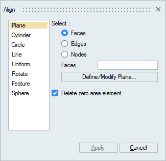
For mesh models, faces or edges or nodes can be moved to the defined plane.
For CAD Parasolid models imported with Save geometry in database option, faces can be aligned to a plane.
Cylinder
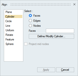
Faces or edges or nodes can be aligned to the defined cylinder.
- Project mid nodes: If the input faces or edges contains higher order elements, the mid nodes can also be aligned by turning ON this toggle. Otherwise the mid nodes will be linearized.
Circle
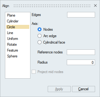
This tool is used to align the nodes on edges to a circle.
- Axis
The axis and radius of the circle can be defined using any one of the following options.
- Nodes: Select three nodes forming a circle.
- Arc edge: Select an arc edge.
- Cylindrical face: Select a cylindrical
face.
- Offset to node: This option is used to align the input edges onto a plane perpendicular to the defined axis and going through the given node. Suppose if the nodes on the input edges are not in a plane, then this option is mandatory.
- Project mid nodes: If the input edges contains higher order elements, the mid nodes can also be aligned by turning ON this toggle. Otherwise the mid nodes will be linearized.
Line
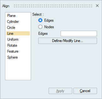
This tool is used to straighten the edges or to move nodes to a straight line.
Uniform
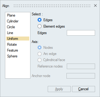
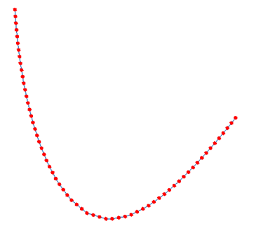
This tool is used to uniformly position the nodes on the selected edges or element edges.
- Axis
If the selected edges form a closed loop, then you have to define an axis to uniformly position along the angular direction. The axis can be defined by selecting 2 nodes or an arc edge or a cylindrical face. Anchor node position will be fixed while the rest will be uniformly positioned.
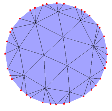
Example1
- Input
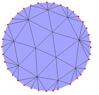
- Output
Example2
- Input
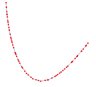
- Output
Example3
- Input
- Output
Rotate
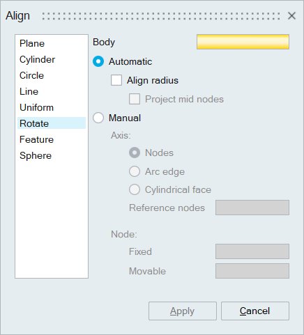
This tool can be used to rotate all the nodes in a body by an angle about an axis. This tool can be used where we have matching mesh between a bolt and the thread portion on the block, however the bolt mesh have some deviation along the axis. In this case we can rotate the bolt to have matching node positions. “Align radius” option will align the cylinder of bolt to bolt hole. “Project mid nodes” will align mid nodes to cylinder.
- Axis
The axis can be defined by selecting 2 nodes or an arc edge or a cylindrical face.
- Node
You have to select a Fixed node and a Movable node. The selected body is rotated for the angle made by these two nodes about the axis.
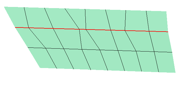
Example:
- Input
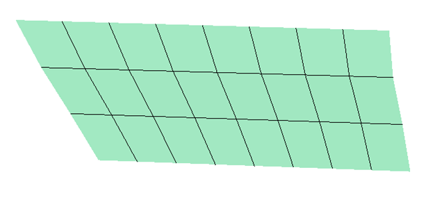
- Output
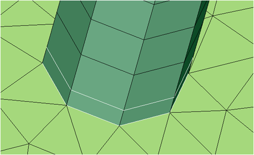
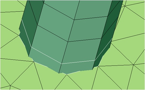
Feature
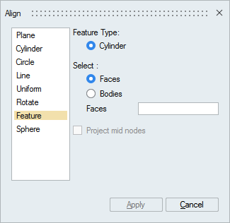
This tool will make sure that the nodes on a cylindrical face lies exactly on the cylinder.
- Project mid nodes
If the input bodies or faces contains higher order elements, the mid nodes can also be aligned by turning ON this toggle. Otherwise the mid nodes will be linearized.
Sphere
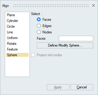
Faces or edges or nodes can be aligned to the defined sphere.
- Project mid nodes
If the input faces or edges contains higher order elements, the mid nodes can also be aligned by turning ON this toggle. Otherwise the mid nodes will be linearized.