Intersections
![]()
Introduction
Intersections between FE bodies, need to be resolved before generating a volume mesh. The identification and resolving process will be difficult for models with a large body count. Using this tool, one can find intersections and resolve them quickly.
In the case of the CAD model input, it is only possible to identify the intersecting faces/bodies in the assembly.
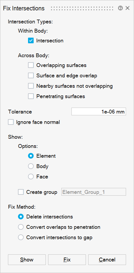
- Intersection Types
The steps to resolve intersections within a body, and across bodies are different, so options are provided to process them separately.
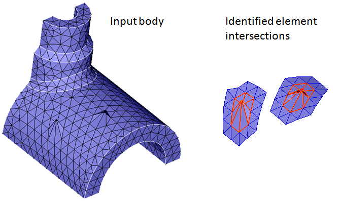
- Within Body
This type is used to identify all element intersections within a body.
- Across Body
Select the type of intersection between bodies to use. You can select more than one intersection type to process.
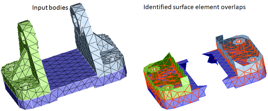
- Overlapping surfaces
The overlap of surface elements from different bodies can be identified using this option. If the angle between the element normal (elements are from different bodies) is less than 10 or greater than 170 degrees, then these elements are identified as overlapping elements.
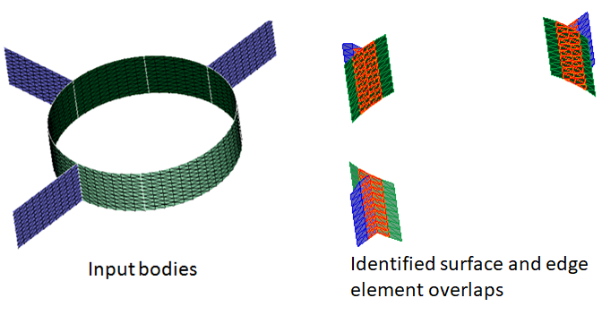
- Surface and edge
overlap
The overlapping elements between topological edges and surface elements across bodies can be identified using this option.
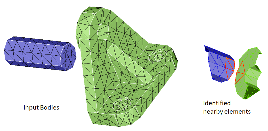
- Nearby surfaces not
overlapping
Near by elements within the given tolerance can be identified using this option. These are elements that do not belongs to surface overlap, surface and edge overlap and penetration.
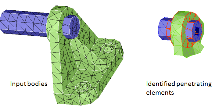
- Penetrating surfaces
These are element intersections that penetrate each other and do not depend on the tolerance used.
- Overlapping surfaces
- Within Body
- Tolerance
Intersection is based on this value. It is assumed that the intersection tolerance is smaller than the elements that are searched for intersection. A tolerance less than 10 percent of the average element size is a recommended.
- Ignore face normal
This option is used to identify overlapping elements regardless of the face normal and this option is enabled only for across body intersection type. If the toggle is turned ON, user can only do Show (or) Delete intersections.
- Show Options
The Show will display the intersecting elements/bodies/faces based on the chosen option.
- Element
Intersecting elements gets displayed for this option.
- Body / Face
These options add the found bodies or face groups to the Output List. One can go through the identified body pairs in the output list and resolve the penetrations by doing a Boolean operation and resolve the overlaps by converting them into penetration.
- Create group
Turn on this toggle to create a group for the identified elements or faces based on the selected option.
- Element
- Fix Method
Intersections can be fixed by using any one of the following methods.
- Delete intersections
After identifying the intersecting elements, use this option to delete intersecting elements.
- When intersecting elements are identified within a body, then all intersecting elements will be deleted.
- When intersecting elements are identified across bodies, then elements on only one side is deleted.
- Surface and edge overlap, elements on the face will be deleted.
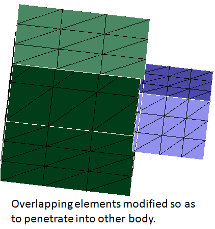
- Convert overlaps to penetration
When two adjacent FE bodies are penetrating then the two bodies can be combined by Boolean operations. So if overlapping are found, it will be useful to convert them to penetrations. This option converts the overlaps to penetration by moving the nodes of one of the body into the other. Note that an internal tolerance, 10% of the average element size is used to offset the elements. The tolerance specified in this dialog box is not used to define the extent of the node offset.
It is possible that the overlapping elements are not completely converted into penetration. Use the tool again to check whether the operation is completed. On completion, a message will be posted indicating that there are no more overlaps. If overlaps are still present, a manual cleanup using node move, collapse, is recommended to fix the problem.
A permanent group for the modified elements can be created by checking the Create group check box and entering a group name.
Example:
Convert overlaps to penetration 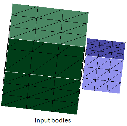
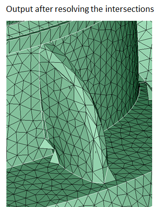
- Convert intersections to gap
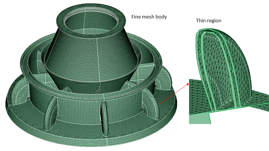
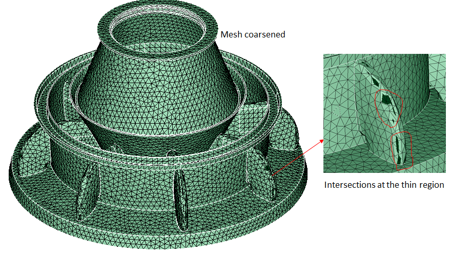
Coarse mesh on a FE body results into formation of intersections at the curved surfaces of thin regions. These intersections can be resolved using this option.
Example:
- Delete intersections