Impose Velocity
![]()
Introduction
This panel is used to define an arbitrary number of regions to define the fluid velocity.
Description
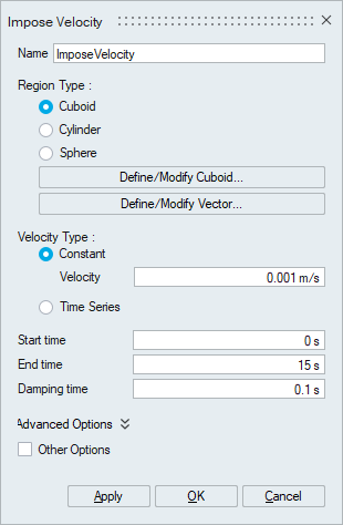
The fluid velocity region can be specified in a rectangular or spherical shape and it hard-imposes a velocity on all fluid particles which are within the prescribed region. The easiest analogy is a pump mechanism (momentum source), except that there are no moving parts involved.
Following imposed velocity types can be defined,
- PARALLELEPIPEDVEL
- CYLINDERVEL
Velocity Type
- Constant - Imposed velocity inside the region.
- Time Series - Defines variable velocity inside the imposed region.
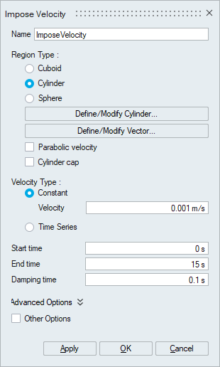
Parabolic velocity – Enables a parabolic velocity profile when cylindrical imposed velocity regions are used.
Cylinder cap - Controls adding of hemispherical caps on the cylinder bases (resulting in a pill-shape geometry). The caps are added to both sides of the cylinder.
Start Time / End Time - Specifies the start and finish times which define the window where the impose region is active.
Damping Time - This parameter specifies a time window for the acceleration of the fluid. At the start time the velocity will ramp up from zero to the specified value over this time. This minimizes pressure fluctuations and instabilities caused by instantaneous changes in velocity.
Advanced Options
- Mode - Defines the mode of the impose region, are the specified values added or set inside the impose region. Options are SET, ADD.
- Constraint - Defines the constraint of the impose region, are the specified values strictly or loosely imposed in the region. Options are: LOOSE, STRICT.
- Moving body motion to follow - Impose regions can follow a MOVINGWALL phase with a predefined motion.