Gas Venting
![]()
Introduction
Battery venting is a critical safety mechanism designed to prevent catastrophic failure in lithium-ion cells during thermal abuse scenarios. Cells are typically equipped with vents, such as pressure relief valves or rupture discs, that activate when internal pressure exceeds a predefined threshold. These components release built-up gases – potentially flammable - to reduce the risk of explosion and catastrophic failure. However, venting can also introduce new risks, such as accelerating the propagation of thermal runaway. As a result, the design and placement of venting pathways are crucial in cell and pack architecture. Despite their importance, accurately modeling the physics of gas venting remains a significant challenge. The SimLab venting model alleviates some of these challenges to help aid cell and pack design.
- Experimental Venting Gas Data Model: This model relies on experimentally measured venting parameters, such as the mass flow rate of vented gases (e.g., obtained using high-speed mass balance measurements) and vent gas temperature (e.g., measured with thermocouples). Venting is triggered based on cell temperature.
- Pressure-Reaction Model (Beta): This physics-based model simulates gas venting by modeling electrolyte, gas generation, and accumulation, leading to pressure buildup and subsequent venting. The venting is triggered when internal pressure exceeds a critical threshold. This method requires gas composition analysis, such as Gas Chromatography-Mass Spectrometry (GC-MS) analysis performed post-ARC testing.
- First venting (Controlled Venting):During the self-heating stage, the cell may undergo controlled venting through a mechanical safety mechanism, such as a pressure relief valve opening or a burst disc rupturing. This feature is designed to relieve internal pressure and prevent structural failure of the cell.
- Second venting (Uncontrolled Gas Release):If self-heating progresses to full thermal runaway, an uncontrolled and violent release of gases occurs because of rapid decomposition reactions within the cell. This event is typically accompanied by uncontrolled heat generation and other catastrophic failures.
Venting Gas Data Model
The Venting Gas Data model simulates the venting behavior of lithium-ion cells during thermal runway, incorporating experimental data and key simplifying assumptions (e.g. the dynamics of venting are the same for all cells in the module) to maintain computational efficiency while capturing essential physical phenomena.
The input panel is shown below,
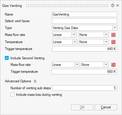
Select vent faces: Surface mesh that represents the venting surface. These faces are at the interface between the battery and the fluid volume.
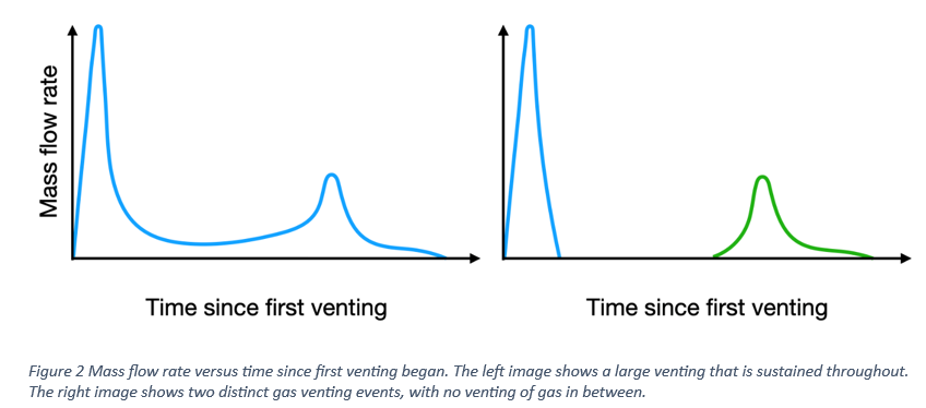
Mass flow rate: Table of mass flow rate vs time. The mass flow rate data typically corresponds only to the venting event, meaning that time = 0 in the data does not represent the physical start time of the simulation. Instead, it marks the onset of venting, which occurs once the cell reaches a specified temperature. There is no restriction on the duration or structure of the venting data. For example, the input table could include multiple venting events or sustained gas release right through to thermal runaway. This mass flow rate could be obtained, as an example, by monitoring the mass of the cell during a controlled temperature ramp or other methods to induce thermal runaway. Some examples of mass flow rate curves are shown in Figure 2.
Temperature: Table of gas temperature vs time. The temperature data represents the gas temperature at the vent opening, typically measured using a thermocouple during the same controlled temperature rise experiment used to collect the mass flow rate data.
Trigger temperature: The Temperature at which the valve or burst disc opens. As an example, this temperature can often be read from ARC data where a small dip is evident during the self-heating stage.
- Mass flow rate: Table of mass flow rate vs time for the second venting event.
- Trigger temperature: Temperature at which the second venting event occurs.
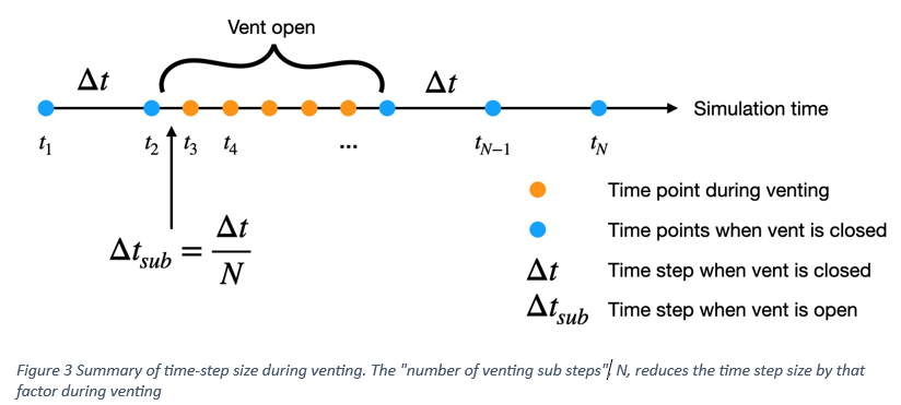
Number of venting sub steps: Specifies how many time steps are taken during the venting process. This value should reflect the desired level of detail in the simulation. For instance, because venting often occurs over a very short time, using a higher number of sub-steps can help accurately capture transient behavior. A summary of the venting sub steps is given in Figure 3.
Include mass loss during venting: Check this box to enable mass loss resulting from material being vented from the battery. The mass loss is calculated by integrating the venting flow rate over time, and the density of the jelly roll is updated accordingly to reflect the reduced mass.
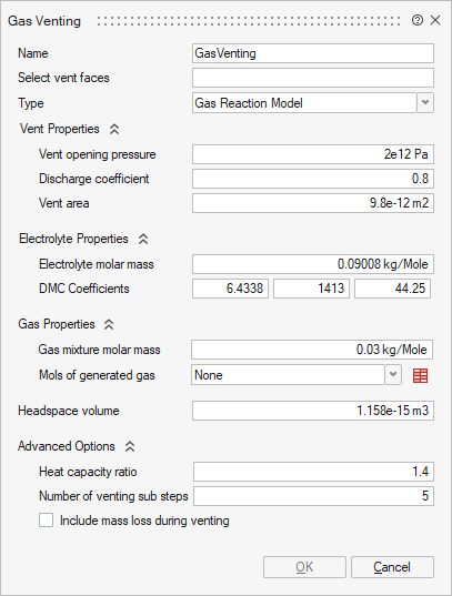
Gas Reaction Model (Beta)
The gas reaction model simulates gas venting during thermal runaway by using a physics-based modeling approach to model gas pressure within the headspace of a cell and subsequent release (venting) of the hot gas through a valve/rupture disc. The input panel for this model is shown below,
- Isentropic - Use the isentropic nozzle flow model for gas velocity.
- Forchheimer - Apply Forchheimer’s model for gas velocity for 1st
venting.
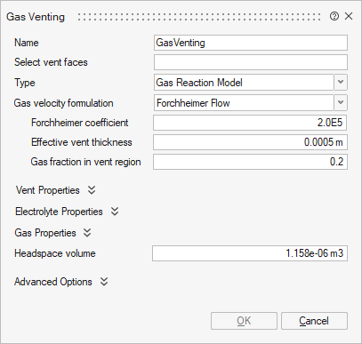
Forchheimer coefficient: Forchheimer’s coefficient for the specific cell.
Effective vent thickness: Effective thickness of a porous medium.
Gas fraction in vent region: Fraction of gas in a cell volume.
Vent opening pressure: Pressure at which the valve or burst disc opens/ruptures.
Discharge coefficient: Cd of the vent that accounts for the reduction in the mass flow rate compared to a theoretical mass flow rate
Vent area: Area of the valve opening or rupture point.
Electrolyte molar mass: Molar mass of the electrolyte
-
Dimethyl Carbonate (DMC)
DMC coefficients: Fitting coefficients for the Antoine equation describing the relationship between electrolyte pressure (P) and temperature (T):
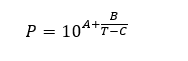
Where A, B, and C represent the fitting coefficients in the panel from left to right, as shown below.

- Ethylene Carbonate (EC)
EC Coefficients: Fitting coefficients for Antoine’s equation describing the partial pressure of an EC electrolyte vapor.
- Dimethyl and Ethylene Mixture: Fitting coefficients for Antoine’s equation describing the partial pressure of DMC-EC mixed electrolyte vapor; the first three values correspond to DMC.
Molar Fraction: Mole fraction of the DMC-EC mixed vapor; the first value corresponds to DMC. DMC-EC coefficients must be defined.
Gas mixture molar mass: Molar mass of the generated gas mixture
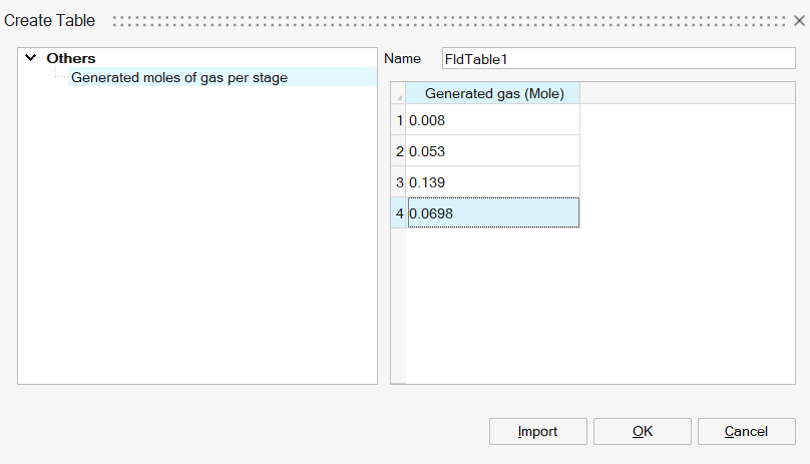
Mols of generated gas: A table specifying the moles of gas generated at each stage of thermal runaway. This table must align with the number of stages defined in the thermal runaway model; for example, a model with four stages must provide gas generation data for each of those four stages. An example input for a four-stage gas generation model is shown below:
Adaptive time-step trigger zone (%): Time-step adaptation window before vent valve or burst disc opening, expressed as a percentage of the current pressure relative to the opening pressure.
Headspace volume: Volume of the headspace where gases accumulate during the self-heating phase of thermal runaway
Number of venting sub steps: Specifies how many time steps are taken during the venting process. This value should reflect the desired level of detail in the simulation. For instance, because venting often occurs over a very short time, using a higher number of sub-steps can help accurately capture transient behavior. The actual time-step will vary automatically due to some sharp transient behavior when the valve/rupture disc opens.
Include mass loss during venting: Check this box to enable mass loss resulting from material being vented from the battery. The mass loss is calculated by integrating the venting flow rate over time, and the density of the jelly roll is updated accordingly to reflect the reduced mass.