Electrostatic Mesh
![]()
Electrostatic Mesh
The electrostatic mesh provides a one-click solution to generate the surface Tri mesh for Electrostatic analysis.
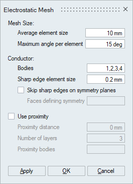
Mesh size
Electrostatic mesh is supported only for CAD bodies. By default, all the bodies in the model will be meshed.
-
Average element size
The average element size is the average element edge length for Tri elements. The element edge length will vary between (average element size)*sqrt(2) and (average element size)/sqrt(2).
-
Maximum angle per element
The maximum angle per element will control the number of elements along the fillet curvature direction. The default maximum angle per element is 15 degrees.
Conductor
-
Sharp edge element size
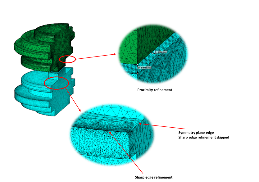
Convex edges on the conductors will be meshed with Sharp edge element size. Default size is 0.2.
-
Skip sharp edges on symmetry planes
This option will skip the convex edges on the symmetry plane from the sharp edge refinement.
Use proximity
This option will refine mesh on the faces that are in given proximity range. These refinements at the surface mesh will ensure getting required number of Tet layers while volume meshing.
-
Proximity distance
Proximity distance is the range of closeness between surfaces that are to be considered for mesh refinement.
-
Number of layers
Number of layers will ensure minimum number of layers created between the faces within the given proximity range.
Example