
Draft
Add draft to one or more faces of a part.
Draft Along a Neutral Plane
You can use a reference plane or select an existing face in the model as the neutral plane.
- First, create a reference plane. Skip this step if you want to designate an existing face in the model as the neutral plane.
-
On the Geometry ribbon, select the Draft tool.

Note: The tool may be hidden in the dropdown menu. To access the dropdown menu, you can do one of the following:- Select
 at the lower-right corner of the
currently displayed tool.
at the lower-right corner of the
currently displayed tool. - Click and hold the currently displayed tool.
Tip: To find and open a tool, press Ctrl+F. For more information, see Find and Search for Tools.The guide panel appears.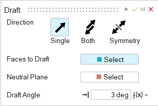
- Select
- In the guide panel, select the Neutral Plane tab.
-
Choose a direction:
- Single (default): Create the draft on one side of the neutral plane.
- Both: Create the draft on both sides of the neutral plane.
- Symmetry: Create the draft symmetrically on both sides of the neutral plane.
-
In the guide panel, adjust the Draft Angle.
Note: To reverse the draft direction of a selected face, click Reverse Draft Direction
 in the microdialog.
 -
Select one or more faces to draft:
- Next to Faces to Draft, click the Select button.
- Select one or more faces.
Note: To deselect a feature, hold down Ctrl while clicking. To clear all selected features, click Clear Selection in the microdialog. -
Designate the neutral plane:
- Next to Neutral Plane, click the Select button.
- If you created a reference plane in Step 1, select it. Otherwise, select an existing face in the model.
A blue arrow appears, indicating the draw direction. - Click Apply.
- Right-click and mouse through the check mark to exit, or double-right-click.
Draft Along a Parting Line
You can select a line in the model to apply draft to the adjacent faces.
- Optional: First, create a line. Skip this step if you want to designate an existing line in the model.
-
On the Geometry ribbon, select the Draft tool.
Note: The tool may be hidden in the dropdown menu. To access the dropdown menu, you can do one of the following:- Select at the lower-right corner of the
currently displayed tool.
- Click and hold the currently displayed tool.
Tip: To find and open a tool, press Ctrl+F. For more information, see Find and Search for Tools.The guide panel appears.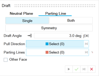
- Select
- In the guide panel, select the Parting Line tab.
-
Choose a direction:
- Single (default): Create the draft on one side of the parting line.
- Both: Create the draft on both sides of the parting line with independent draft angles.
- Symmetry: Create the draft symmetrically on both sides of the parting line.
-
In the guide panel, adjust the Draft Angle.
Note: To reverse the draft direction of a selected face, click Reverse Draft Direction in the microdialog.
-
Define the pull direction:
- Next to Pull Direction, click the Select button.
- Select a face in the model.
A blue arrow appears, indicating the pull direction. -
Designate the parting line:
- Next to Parting Lines, click the Select button.
- If you created a parting line in Step 1, select it. Otherwise, select an
existing line in the model.Note: To include edges that are tangent to the selected parting line, select Tangent Propagation
 in the
microdialog.
in the
microdialog. 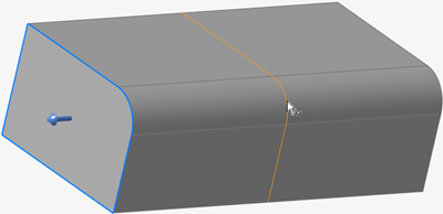
The face of the model is displayed in blue, and the Draft Angle is applied. - Select the Other Face checkbox if you want to apply the draft to the face on the opposite side of the parting line.
- Click Apply.
- Right-click and mouse through the check mark to exit, or double-right-click.