
Loft
Create a solid loft or a lofted surface from profiles and guide curves. Create a new part from the loft or combine, subtract, or intersect the loft with existing parts.
-
On the Geometry ribbon, select the Loft tool.

Note: The tool may be hidden in the dropdown menu. To access the dropdown menu, you can do one of the following:- Select
 at the lower right corner of the
currently displayed tool.
at the lower right corner of the
currently displayed tool. - Click and hold the currently displayed tool.
Tip: To find and open a tool, press Ctrl+F. For more information, see Find and Search for Tools.The guide panel appears.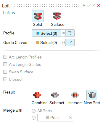
- Select
-
Choose the entity type that you'd like to create:
- Solid: Loft as a solid.
- Surface: Loft as a surface.
-
Select a Profile. By default,
Select is automatically turned on. Do one of the
following:
- If you selected Solid in the last step, click the Select collector and select a closed sketch or a planar surface.
- If you selected Surface in the last step, select a planar edge, closed/open sketch, or a planar surface.
- (Optional): Select
 so that clicking an edge will also select
edges connected to the profile.
so that clicking an edge will also select
edges connected to the profile.
Note: To deselect, hold down Ctrl while clicking. -
Choose Guide Curves:
-
Select a sketch or an edge. The plane in which the profile lies must
intersect the guide curve.
Note: To deselect, hold down Ctrl while clicking. To clear all selected features, click
 next to the
Select button in the guide panel.
next to the
Select button in the guide panel. -
(Optional): Select
Tangent Propagation so that clicking an edge will
also select all of its tangent edges.
-
Select a sketch or an edge. The plane in which the profile lies must
intersect the guide curve.
-
Edit the loft:
To Do this Notes Reselect profiles or rails - In the guide panel, click the Select button next to Profiles or Guide Curves.
- Select the profiles or rails you want to add or remove.
Define other options In the guide panel, select from the following options: - Arc Length Profiles: Evenly space the isoparms in the direction of the profiles.
- Arc Length Guides: Evenly space the isoparms in the direction of the guide curves.
- Swap Surface: Quickly interchange the profiles and guide curves to get a preferred shape.
- Closed: Close the loft.
Invert the direction of a profile or guide curve - Select the vertex of the profile or the guide curve.
- In the microdialog, turn on Invert Direction
The direction of the arrow on the profile or guide curve indicates its orientation.
In most cases, the optimal orientation of each profile is internally calculated so that the resulting surface is not twisted. In some cases, inverting a profile's direction will cause the loft to fail. Apply a constraint to a selected profile - Select the vertex on the profile or the profile itself.
- In the microdialog, for Constraints, choose one of
the following:
- Position (G0): No constraints are set; the loft surface is connected to the surface edge, but not tangent to it.
- Tangent (G1): The loft
surface is made tangent to the surface edge but
does not follow the curvature of the adjacent
surface. A box is displayed on the profile to
indicate that a tangency constraint was
applied.
- Curvature (G2): The
loft surface is made tangent to the surface edge
and follows the curvature of the adjacent surface.
A circle is displayed on the profile to indicate
that a curvature constraint was applied.
- Normal: The loft surface is made perpendicular to all vertices. This option is useful for planar curves.
- Free Tangent Vector: The loft surface is made tangent to a selected vector. You can manipulate both the magnitude and direction of the selected vector.
To invert the direction of the profile's tangent, in the microdialog click Invert Tangent  .
.Modify the tangent magnitude of a selected profile - Select the vertex on the profile.
- In the microdialog, enter a Magnitude.
Refine the shape when the selected profile or edge is a periodic curve Drag the seam along the profile or edge. -
Choose a Result type:
- Combine (only available for Solids): Combine the loft with the existing parts.
- Merge (only available for surfaces): Merge the lofted surface with existing parts
- Subtract (only available for Solids): Carve out the loft from the existing parts.
- Intersect (only available for Solids): Retain only the intersecting portions of the loft and the existing parts.
- New Part: Create a new part from the loft.
-
If you selected Solids, choose a
Merge method:
- All Parts (default): Merge the loft with all parts that touch it.
- Selected Parts: Select the radio button to merge the loft with selected parts. Then select the parts that you’d like to merge the loft with.
-
If you selected Combine, choose how to combine the
lofted shape:
- Target: Select the checkbox and use the collector
to select the part you want to merge into.Note: When the Selected Parts radio button is selected, the target part must be one of the selected parts before you can apply the change. When All Parts is selected, you can select any part as the Target.
- Target: Clear the checkbox to merge parts automatically.
- Target: Select the checkbox and use the collector
to select the part you want to merge into.
- Click Apply.
- Right-click and mouse through the check mark to exit, or double-right-click.