
Deform
Twist, bend, taper, shear, stretch, or drape parts within a specified region (deformation zone).
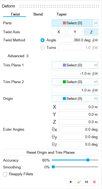
Twist
Twist one or more parts along an axis.
-
On the Geometry ribbon, select the Deform tool.

Tip: To find and open a tool, press Ctrl+F. For more information, see Find and Search for Tools. -
In the guide panel, select the Twist tab.
- Select one or more parts.
-
Select a Deform Axis:
- XYZ: Deform the parts with respect to the selected x-, y-, or z-axis.
- Custom: Deform the parts with respect to the linear edge or axis you select with the Deform Axis collector.
-
Select a Twist Method:
- Angle: The angle and number of turns are interdependent. If you edit the angle, the number of turns updates automatically and vice versa.
- Turns: The angle and number of turns are interdependent. If you edit the angle, the number of turns updates automatically and vice versa.
-
Configure the Advanced options:
Tip: To modify the deformation zone, adjust Trim Plane 1 and 2.
Option Description Trim Plane 1 Select Trim Plane 1: Select a point to position Trim Plane 1. The deformation is applied between Trim Plane 1 and Trim Plane 2. Trim Plane 1 Offset Distance: Enter the offset distance between Trim Plane 1 and the origin.Tip: You can also drag the plane in the workspace: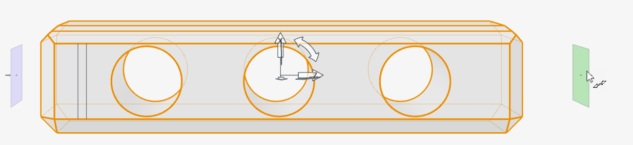
Trim Plane 2 Select Trim Plane 2: Select a point to position Trim Plane 2. The deformation is applied between Trim Plane 1 and Trim Plane 2. Trim Plane 2 Offset Distance: Enter the offset distance between Trim Plane 2 and the origin.
Origin Select Origin: Select a point as the origin. Trim Plane 1 and Trim Plane 2 are offsets from the deformation’s origin. Adjust the origin to simultaneously move both trim planes. Euler Angles X
Enter the x-coordinate of the origin.
Y
Enter the y-coordinate of the origin.
Z
Enter the z-coordinate of the origin.
θx
Enter the global x rotation angle.
θy
Enter the global y rotation angle.
θz
Enter the global z rotation angle.
Reset Origin and Trim Planes Reset the origin and the trim planes to the default positions. Accuracy Modify the tolerance. The maximum value is 100%. Changing the Accuracy [%] may slow down the operation or cause it to fail. Note: If a deformation fails, decrease the Accuracy setting and try again.Reapply Fillets Reapply the fillet operation. - Right-click and mouse through the check mark to exit, or double-right-click.
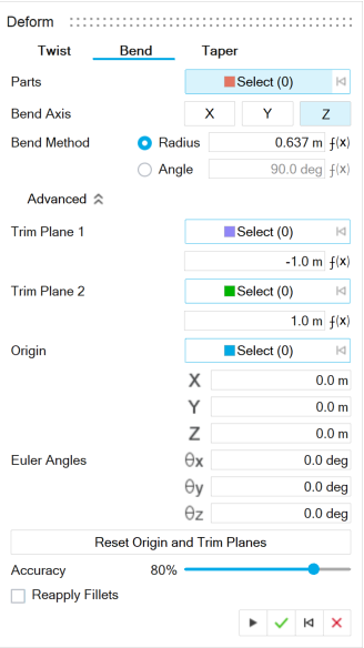
Bend
Bend one or more objects with respect to an axis.
-
On the Geometry ribbon, select the Deform tool.
Tip: To find and open a tool, press Ctrl+F. For more information, see Find and Search for Tools. -
In the guide panel, select the Bend tab.
- Select one or more parts.
-
Select a Deform Axis:
- XYZ: Deform the parts with respect to the selected x-, y-, or z-axis.
- Custom: Deform the parts with respect to the linear edge or axis you select with the Deform Axis collector.
-
Select a Bend Method:
- Radius: Enter the bend radius.
- Angle: Enter the bend angle.
-
Configure the Advanced options:
Tip: To modify the deformation zone, adjust Trim Plane 1 and 2.
Option Description Trim Plane 1 Select Trim Plane 1: Select a point to position Trim Plane 1. The deformation is applied between Trim Plane 1 and Trim Plane 2. Trim Plane 1 Offset Distance: Enter the offset distance between Trim Plane 1 and the origin.Tip: You can also drag the plane in the workspace:Trim Plane 2 Select Trim Plane 2: Select a point to position Trim Plane 2. The deformation is applied between Trim Plane 1 and Trim Plane 2. Trim Plane 2 Offset Distance: Enter the offset distance between Trim Plane 2 and the origin.
Origin Select Origin: Select a point as the origin. Trim Plane 1 and Trim Plane 2 are offsets from the deformation’s origin. Adjust the origin to simultaneously move both trim planes. Euler Angles X
Enter the x-coordinate of the origin.
Y
Enter the y-coordinate of the origin.
Z
Enter the z-coordinate of the origin.
θx
Enter the global x rotation angle.
θy
Enter the global y rotation angle.
θz
Enter the global z rotation angle.
Reset Origin and Trim Planes Reset the origin and the trim planes to the default positions. Accuracy Modify the tolerance. The maximum value is 100%. Changing the Accuracy [%] may slow down the operation or cause it to fail. Note: If a deformation fails, decrease the Accuracy setting and try again.Reapply Fillets Reapply the fillet operation. - Right-click and mouse through the check mark to exit, or double-right-click.
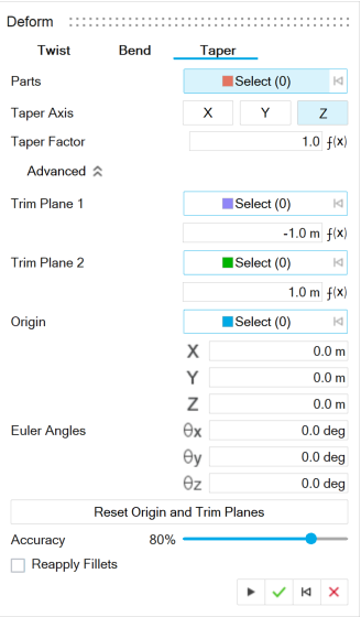
Taper
Make one or more objects progressively smaller toward one end.
-
On the Geometry ribbon, select the Deform tool.
Tip: To find and open a tool, press Ctrl+F. For more information, see Find and Search for Tools. -
In the guide panel, select the Taper tab.
- Select one or more parts.
-
Select a Deform Axis:
- XYZ: Deform the parts with respect to the selected x-, y-, or z-axis.
- Custom: Deform the parts with respect to the linear edge or axis you select with the Deform Axis collector.
- Define the Taper Factor.
-
Configure the Advanced options:
Tip: To modify the deformation zone, adjust Trim Plane 1 and 2.
Option Description Trim Plane 1 Select Trim Plane 1: Select a point to position Trim Plane 1. The deformation is applied between Trim Plane 1 and Trim Plane 2. Trim Plane 1 Offset Distance: Enter the offset distance between Trim Plane 1 and the origin.Tip: You can also drag the plane in the workspace:Trim Plane 2 Select Trim Plane 2: Select a point to position Trim Plane 2. The deformation is applied between Trim Plane 1 and Trim Plane 2. Trim Plane 2 Offset Distance: Enter the offset distance between Trim Plane 2 and the origin.
Origin Select Origin: Select a point as the origin. Trim Plane 1 and Trim Plane 2 are offsets from the deformation’s origin. Adjust the origin to simultaneously move both trim planes. Euler Angles X
Enter the x-coordinate of the origin.
Y
Enter the y-coordinate of the origin.
Z
Enter the z-coordinate of the origin.
θx
Enter the global x rotation angle.
θy
Enter the global y rotation angle.
θz
Enter the global z rotation angle.
Reset Origin and Trim Planes Reset the origin and the trim planes to the default positions. Accuracy Modify the tolerance. The maximum value is 100%. Changing the Accuracy [%] may slow down the operation or cause it to fail. Note: If a deformation fails, decrease the Accuracy setting and try again.Reapply Fillets Reapply the fillet operation. - Right-click and mouse through the check mark to exit, or double-right-click.
Shear
Tilt one or more objects at an angle with respect to an axis.
-
On the Geometry ribbon, select the Deform tool.
Tip: To find and open a tool, press Ctrl+F. For more information, see Find and Search for Tools. -
In the guide panel, select the Shear tab.
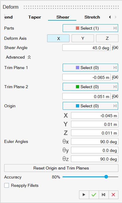
- Select one or more parts that you want to shear.
-
Select a Deform Axis:
- XYZ: Deform the parts with respect to the selected x-, y-, or z-axis.
- Custom: Deform the parts with respect to the linear edge or axis you select with the Deform Axis collector.
- Define the Shear Angle.
-
Configure the Advanced options:
Tip: To modify the deformation zone, adjust Trim Plane 1 and 2.
Option Description Trim Plane 1 Select Trim Plane 1: Select a point to position Trim Plane 1. The deformation is applied between Trim Plane 1 and Trim Plane 2. Trim Plane 1 Offset Distance: Enter the offset distance between Trim Plane 1 and the origin.Tip: You can also drag the plane in the workspace:Trim Plane 2 Select Trim Plane 2: Select a point to position Trim Plane 2. The deformation is applied between Trim Plane 1 and Trim Plane 2. Trim Plane 2 Offset Distance: Enter the offset distance between Trim Plane 2 and the origin.
Origin Select Origin: Select a point as the origin. Trim Plane 1 and Trim Plane 2 are offsets from the deformation’s origin. Adjust the origin to simultaneously move both trim planes. Euler Angles X
Enter the x-coordinate of the origin.
Y
Enter the y-coordinate of the origin.
Z
Enter the z-coordinate of the origin.
θx
Enter the global x rotation angle.
θy
Enter the global y rotation angle.
θz
Enter the global z rotation angle.
Reset Origin and Trim Planes Reset the origin and the trim planes to the default positions. Accuracy Modify the tolerance. The maximum value is 100%. Changing the Accuracy [%] may slow down the operation or cause it to fail. Note: If a deformation fails, decrease the Accuracy setting and try again.Reapply Fillets Reapply the fillet operation. - Right-click and mouse through the check mark to exit, or double-right-click.
Stretch
Stretch one or more objects along a curve.
-
On the Geometry ribbon, select the
Deform tool.
Tip: To find and open a tool, press Ctrl+F. For more information, see Find and Search for Tools. -
In the guide panel, select the Stretch tab.
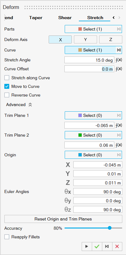
- Select one or more parts that you want to stretch.
-
Select a Deform Axis:
- XYZ: Deform the parts with respect to the selected x-, y-, or z-axis.
- Custom: Deform the parts with respect to the linear edge or axis you select with the Deform Axis collector.
- Select the curve you want to use to stretch the selected parts.
- Define the Stretch Angle to rotate the stretch around the curve.
- Define the Curve Offset to indicate the portion of the curve that will be used to stretch the selected parts.
- Select Stretch along Curve to make the stretch follow the length of the curve.
- Select Move to Curve to move the stretch to align with the curve.
- Select Reverse Curve to invert the stretch direction.
-
Configure the Advanced options:
Tip: To modify the deformation zone, adjust Trim Plane 1 and 2.
Option Description Trim Plane 1 Select Trim Plane 1: Select a point to position Trim Plane 1. The deformation is applied between Trim Plane 1 and Trim Plane 2. Trim Plane 1 Offset Distance: Enter the offset distance between Trim Plane 1 and the origin.Tip: You can also drag the plane in the workspace:Trim Plane 2 Select Trim Plane 2: Select a point to position Trim Plane 2. The deformation is applied between Trim Plane 1 and Trim Plane 2. Trim Plane 2 Offset Distance: Enter the offset distance between Trim Plane 2 and the origin.
Origin Select Origin: Select a point as the origin. Trim Plane 1 and Trim Plane 2 are offsets from the deformation’s origin. Adjust the origin to simultaneously move both trim planes. Euler Angles X
Enter the x-coordinate of the origin.
Y
Enter the y-coordinate of the origin.
Z
Enter the z-coordinate of the origin.
θx
Enter the global x rotation angle.
θy
Enter the global y rotation angle.
θz
Enter the global z rotation angle.
Reset Origin and Trim Planes Reset the origin and the trim planes to the default positions. Accuracy Modify the tolerance. The maximum value is 100%. Changing the Accuracy [%] may slow down the operation or cause it to fail. Reapply Fillets Reapply the fillet operation. - Right-click and mouse through the check mark to exit, or double-right-click.
Drape
Drape one or more parts over a surface.
-
On the Geometry ribbon, select the
Deform tool.
Tip: To find and open a tool, press Ctrl+F. For more information, see Find and Search for Tools. -
In the guide panel, select the Drape tab.
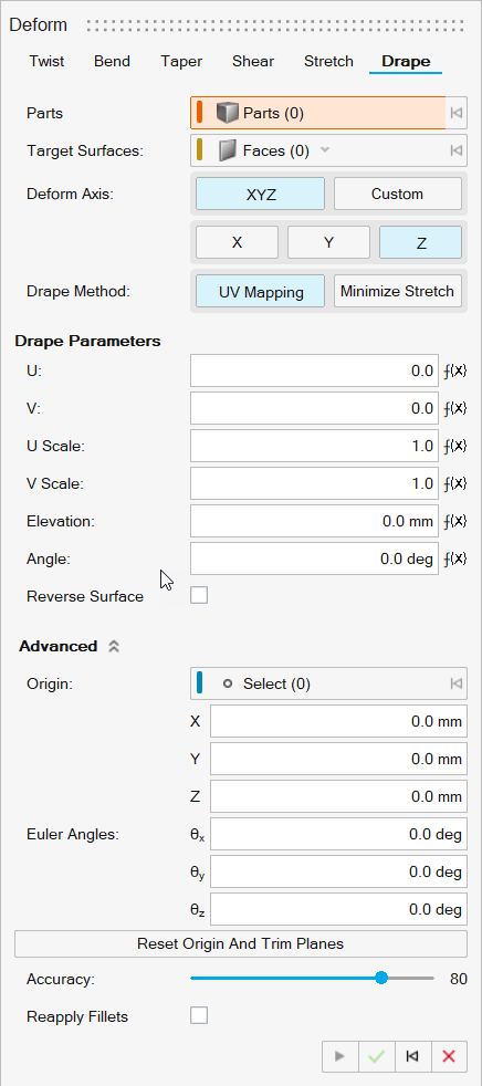
- Use the Parts collector to select one or more parts that you want to drape.
-
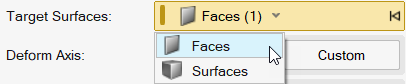
Select the surface where you want to drape the selected parts.
Tip: Click the down arrow to choose whether you want to select faces or surfaces.
-
Select a Deform Axis:
- XYZ: Deform the parts with respect to the selected x-, y-, or z-axis.
- Custom: Deform the parts with respect to the linear edge or axis you select with the Deform Axis collector.
-
Select the Drape Method you want to use:
- Select UV Mapping to position the part on the target surface using NURBS and Parasolid parametrization. This method is more likely to result in distortion of straight lines in the UV plane.
- Select Minimize Stretch to use meshing to
position the part on the target surface. This method minimizes
distortion and stretching.Note: When working with periodic surfaces, use UV Mapping.
-
Adjust the Drape Parameters:
Option Description U Enter an offset to move the deformed part in the U direction. V Enter an offset to move the deformed part in the V direction. U Scale Enter a scaling factor to scale the deformed part in the U direction. V Scale Enter a scaling factor to scale the deformed part in the V direction. Elevation Enter an offset to move the offset the deformed part from the surface. Tip: You can also drag the Elevation handle to adjust the elevation offset: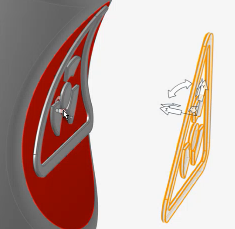
Angle Enter an angle to adjust the position of the deformed part on the surface. Tip: You can also drag the Angle handle to adjust the roation angle: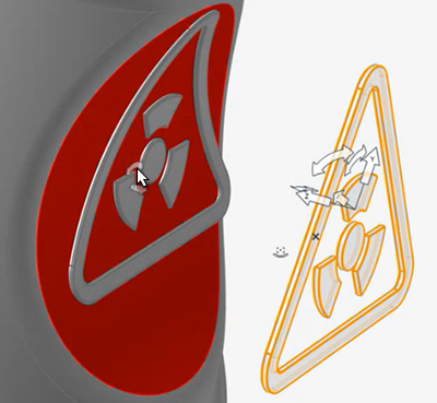
- Select Reverse Surface to drape the part on the opposite surface.
-
Configure the Advanced options:
Option Description Origin Select Origin: Select a point as the origin for the deformed part. Euler Angles X
Enter the x-coordinate of the origin.
Y
Enter the y-coordinate of the origin.
Z
Enter the z-coordinate of the origin.
θx
Enter the global x rotation angle.
θy
Enter the global y rotation angle.
θz
Enter the global z rotation angle.
Reset Origin and Trim Planes Reset the origin and the trim planes to the default positions. Accuracy Modify the tolerance. The maximum value is 100%. Changing the Accuracy [%] may slow down the operation or cause it to fail. Note: If a deformation fails, decrease the Accuracy setting and try again.Reapply Fillets Reapply the fillet operation. - Right-click and mouse through the check mark to exit, or double-right-click.