
/FAIL/GURSON
Block Format Keyword A Gurson-Nahshon-Hutchinson failure model describing the damage evolution in terms of void nucleation and growth in metal plasticity.
The modified Gurson formulation adds additional damage accumulation terms for shear dominated loads, specific treatment under compressive loading, and elastic stiffness loss with damage. Two non-local based regularization methods can be used to avoid mesh dependency.
Format
| (1) | (2) | (3) | (4) | (5) | (6) | (7) | (8) | (9) | (10) |
|---|---|---|---|---|---|---|---|---|---|
| /FAIL/GURSON/mat_ID/unit_ID | |||||||||
| Iloc | |||||||||
| As | Kw | ||||||||
| Rlen | Hchi | ||||||||
| (1) | (2) | (3) | (4) | (5) | (6) | (7) | (8) | (9) | (10) |
|---|---|---|---|---|---|---|---|---|---|
| fail_ID |
Definition
| Field | Contents | SI Unit Example |
|---|---|---|
| mat_ID | Material identifier. (Integer, maximum 10 digits) |
|
| unit_ID | (Optional) Unit identifier. (Integer, maximum 10 digits) |
|
| First Gurson damage
coefficient. Default = 1.5 (Real) |
||
| Second Gurson damage coefficient,
maximum value = 1.02. Default = 1.0 (Real) |
||
| Iloc | Damage variable accumulation method flag.
(Integer) |
|
| Equivalent plastic strain at void
nucleation. (Real) |
||
| As | Linear void nucleation
slope. (Real) |
|
| Kw | Shear damage growth
coefficient. (Real) |
|
| Critical void volume fraction at
void coalescence. (Real) |
||
| Void volume fraction at ductile
failure. (Real) |
||
| Initial void volume
fraction. (Real) |
||
| Rlen | Radius of non-local variable
influence (Iloc
> 1). (Real) |
|
| Hchi | Non-local penalty parameter
(Micromorphic method only,
Iloc =
2). (Real) |
|
| Mesh convergence element length
target. 5
(Real) |
||
| fail_ID | (Optional) Failure criteria
identifier. (Integer, maximum 10 digits) |
Example
/UNIT/123
Example units for DP450 steel (0.6 mm mesh regularization)
                  Mg                  mm                   s
/FAIL/GURSON/1/123
#                 Q1                  Q2                                                        Iloc
                 1.5                 1.0                                                           3
#                Epn                  As                  Kw
                0.27                 1.3                2.65
#                 Fc                  Fr                  F0
             0.16225                 0.2                 0.0
#               Rlen                Hchi              Le_max
                 1.0
Comments
- The Gurson damage model
may only be used with the elasto-plastic material
/MAT/LAW104. The yield surface definition of the
material law is modified by adding the damage evolution terms:
Where,
- ,
- Two Gurson-Tveergard-Needleman parameters,
- Effective damage
- Factor defined as:
- Total void volume fraction that is computed incrementally.
The kinetic equations of the damage factor increments are:- Void nucleation (creation of micro-cavities), decreasing at low
triaxiality.Where, is the stress triaxiality defined as:
Figure 1. Nucleation of cavities 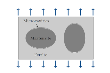
- Void growth at high triaxiality:
Figure 2. Growth of cavities at high triaxiality 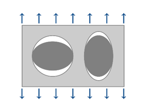
- Additional shear void growth at low triaxiality which is shear
dominated: Where, is a weight function depending on the Lode angle:
Figure 3. Growth of cavities at low triaxiality 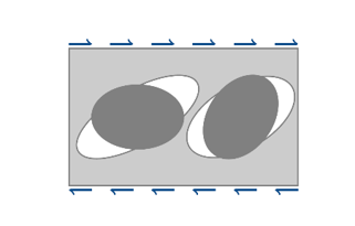
To represent the cavities coalescence when a critical void volume fraction is reached by , the effective damage (which has an influence on the stress computation) is introduced in the model and its expression depends on :
Where, is the total void volume fraction at rupture for which .Figure 4. Coalescence of cavities 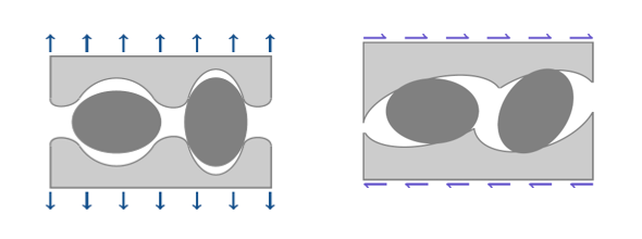
The material fails when the cumulated total damage factor reaches the limit value . The element is then deleted if all gauss points have reached this failure value.
- By default
, the damage variable is calculated step by
step using the local plastic strain values at each integration point.
However, one may want to use non-local regularization which offers mesh size
and the mesh orientation independent results (mesh convergence) for all
meshes using the mesh size
less than equal to the maximum value set by
you
. This maximum mesh size
is then the highest mesh size used for which
results are mesh convergent.
If one of the non-local formulations is used, , the damage increments depend on a regularized nodal “non-local” plastic strain calculated on the entire mesh. The non-local plastic strain at nodes denoted is computed accounting for its own gradient and its local counterpart computed at the Gauss points following the set of equations:
The parameters and are automatically set. You have to set the parameter Rlen (or - Comment 5) which defines a non-local “internal length” which corresponds to a radius of influence in the non-local variable computation. This defines the size of the non-local regularization band (Figure 5).Figure 5. Non-local regularization principle 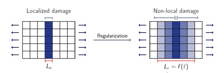
To help choose a value for the parameter Rlen, one may follow the following expression:
- If
, the non-local Micromorphic method will be
used. For this method, the parameter is required,
Hchi. This
parameter and the non-local plastic strain
are introduced in the constitutive equation
as:
Where, is the classical work-hardening function. This newly defined micromorphic work-hardening function Rchi is introduced in the flow stress computation . The parameter Hchi becomes a penalty parameter and if , then and which implies . This method is thermo-dynamically well defined. However, it is hard to identify the input values and it changes the plastic behavior of the model. This is why it is recommended to use the Peerlings method .
- If
, the non-local Peerlings method will be
used. For this method, the parameter
Hchi is used. Only
the non-local length Rlen
is used. This method is simpler than the Micromorphic one. It introduces the
non-local plastic strain in the softening variable kinetic equation (damage
and temperature if thermal effects are considered):
This method is recommended since it is simple to identify the input parameters and does not modify the plastic behavior of the material.
- To set the non-local
length parameter Rlen, you
can choose:
- Directly input the value of Rlen in the input card, if a direct control on this parameter is wanted. In this case, the parameter must be ignored and set to none.
- Input the maximum mesh size for which results have reached mesh convergence. The non-local regularization will then be effective for all mesh sizes such as . In this case Rlen is calculated automatically according to the value of , and the input value of Rlen is ignored. For instance, if you want to get converged and mesh-independent results for a mesh size of 5 mm, mm. In this case, the results will be converged, mesh-size and mesh orientation independent for mm.
- When a non-local regularization is used for shell elements, an
additional regularization is made on the thickness variation computation
avoiding an additional localization issue. In the common local case (Figure 6), the compatibility of thickness
between shell elements is not ensured due to the lack of kinematic equations
in the z-direction, and the thickness variation is locally computed at Gauss
points. By introducing the non-local plastic strain in the “in-thickness”
strain increment, the compatibility is restored, (Figure 7). Where, is the non-local plastic multiplier.
Figure 6. Transverse strain incompatibility (local) 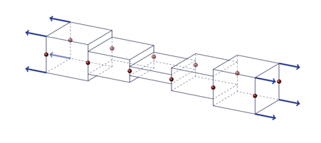
Figure 7. Transverse strain compatibility (non-local) 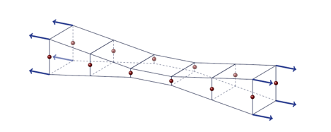
Note: This last point implies that the identified parameters can be used on solid and shells, as results will be identical within the same range of stress triaxiality . - To create a specific damage output in ANIM and H3D files with
/ANIM/ELEM/DAMG, /H3D/SHELL/DAMG
and /H3D/SOLID/DAMG, the total damage is normalized by
its rupture value:
- Using /H3D/ELEM/DAMG, the different damage
variables presented above can be plotted using the keyword
MODE(=I or ALL).
The correspondence between modes and damage variables are:
- MODE1: Void growth volume fraction
- MODE2: Nucleation volume fraction
- MODE3: Shear growth volume fraction
- MODE4: Total void volume fraction
- MODE5: Effective void volume fraction .
Important: The non-local method can be directly activated using the flag for /FAIL/GURSON. A /NONLOCAL/MAT card is not needed in this case.