
/FAIL/TAB2
Block Format Keyword This advanced failure model allows the plastic strain at failure to be defined as a function of stress triaxiality, strain rate, Lode angle, element size, and temperature.
A coupling with stress computation generating a stress softening is also available through different features. It can be fully coupled or triggered by other phenomena like instability strain to control necking. Damage is accumulated based using an exponent evolution. This criterion is compatible with both solids and shells and can be used with non-local regularization.
Format
| (1) | (2) | (3) | (4) | (5) | (6) | (7) | (8) | (9) | (10) |
|---|---|---|---|---|---|---|---|---|---|
| /FAIL/TAB2/mat_ID/unit_ID | |||||||||
| EPSF_ID | FCRIT | FAILIP | PTHICKFAIL | VOLFRAC | |||||
| (1) | (2) | (3) | (4) | (5) | (6) | (7) | (8) | (9) | (10) |
|---|---|---|---|---|---|---|---|---|---|
| N | DCRIT | INST_ID | ECRIT | ||||||
| (1) | (2) | (3) | (4) | (5) | (6) | (7) | (8) | (9) | (10) |
|---|---|---|---|---|---|---|---|---|---|
| FCT_EXP | EXP_REF | EXP | FCT_TEMP | TEMP_REF | FSCALE_TEMP | ||||
| (1) | (2) | (3) | (4) | (5) | (6) | (7) | (8) | (9) | (10) |
|---|---|---|---|---|---|---|---|---|---|
| TAB_EL | IREG | EL_REF | SR_REF1 | FSCALE_EL | |||||
| (1) | (2) | (3) | (4) | (5) | (6) | (7) | (8) | (9) | (10) |
|---|---|---|---|---|---|---|---|---|---|
| SHRF | BIAXF | ||||||||
| (1) | (2) | (3) | (4) | (5) | (6) | (7) | (8) | (9) | (10) |
|---|---|---|---|---|---|---|---|---|---|
| FCT_SR | SR_REF2 | FSCALE_SR | C_JCOOK | ||||||
| (1) | (2) | (3) | (4) | (5) | (6) | (7) | (8) | (9) | (10) |
|---|---|---|---|---|---|---|---|---|---|
| FCT_DLIM | FSCALE_DLIM | ||||||||
| (1) | (2) | (3) | (4) | (5) | (6) | (7) | (8) | (9) | (10) |
|---|---|---|---|---|---|---|---|---|---|
| fail_ID |
Definition
| Field | Contents | SI Unit Example |
|---|---|---|
| mat_ID | Material identifier. (Integer, maximum 10 digits) |
|
| unit_ID | (Optional) Unit identifier. (Integer, maximum 10 digits) |
|
| EPSF_ID | Plastic strain at failure table or
function identifier.
(Integer) |
|
| FCRIT | Scale factor for failure plastic
strain table. Default = 1.0 (Real) |
|
| FAILIP | Number of failed integration point
prior to solid element deletion. Default = 1 (Integer) |
|
| PTHICKFAIL | Percentage of failed layers prior
to shell element deletion. Default = 0.0 (Real) |
|
| VOLFRAC | Volume fraction of failed
integration points prior to solid element deletion (Only used
for fully-integrated and higher order solid elements). Default = 0.0 (Real) |
|
| N | Damage accumulation
exponent. Default = 1.0 (Real) |
|
| DCRIT | Critical damage for stress
softening triggering. Default = 0.0 (Real) |
|
| INST_ID | Instability (necking) plastic
strain table or function identifier.
(Integer) |
|
| ECRIT | Scale factor for necking plastic
strain table identifier. (Real) |
|
| FCT_EXP | Stress softening exponent function
identifier. (Integer) |
|
| EXP_REF | Reference element size for stress
softening exponent function. Default = 1.0 (Real) |
|
| EXP | Scale factor for stress softening
exponent function. Default = 1.0 (Real) |
|
| FCT_TEMP | Temperature dependency function
identifier. (Integer) |
|
| TEMP_REF | Reference temperature for
temperature scaling function. Default = 1.0 (Real) |
|
| FSCALE_TEMP | Scale factor for temperature
scaling function. Default = 1.0 (Real) |
|
| TAB_EL | Element size scaling table or
function identifier.
(Integer) |
|
| IREG | Element size regularization flag.
(Integer) |
|
| EL_REF | Reference element size for size
scaling table. Default = 1.0 (Real) |
|
| SR_REF1 | Reference strain rate for size
scaling table. Default = 1.0 (Real) |
|
| FSCALE_EL | Scale factor for element size
scaling function. Default = 1.0 (Real) |
|
| SHRF | Lower stress triaxiality boundary
for element size scaling. Default = -1.0 (Real) |
|
| BIAXF | Upper stress triaxiality boundary
for element size scaling. Default = 1.0 (Real) |
|
| FCT_SR | Strain rate dependency function
identifier. If the first value of the strain rate is negative in FCT_SR, logarithmic scale is assumed. (Integer) |
|
| SR_REF2 | Reference strain rate for strain
rate dependency function. Default = 1.0 (Real) |
|
| FSCALE_SR | Scale factor for strain rate
dependency function. Default = 1.0 (Real) |
|
| C_JCOOK | Johnson-Cook strain rate dependency
factor. Default = 0.0 (Real) |
|
| FCT_DLIM | Damage limit function
identifier. (Integer) |
|
| FSCALE_DLIM | Damage limit function scale
factor. Default = 1.0 (Real) |
|
| fail_ID | (Optional) Failure criteria
identifier. 14 (Integer, maximum 10 digits) |
Example (Steel)
#RADIOSS STARTER
#---1----|----2----|----3----|----4----|----5----|----6----|----7----|----8----|----9----|---10----|
/UNIT/1
unit for mat
#              MUNIT               LUNIT               TUNIT
                  kg                  mm                  ms
#---1----|----2----|----3----|----4----|----5----|----6----|----7----|----8----|----9----|---10----|
/MAT/PLAS_JOHNS/1/1
Steel
#              RHO_I
              7.8E-6                   0
#                  E                  Nu     Iflag
                 210                  .3         0
#                  a                   b                   n           EPS_p_max            SIG_max0
                  .4                  .5                  .5                   0                   0
#                  c           EPS_DOT_0       ICC   Fsmooth               F_cut               Chard
                   0                   0         0         0                   0                   0
#                  m              T_melt              rhoC_p                 T_r
                   0                   0                   0                   0
#---1----|----2----|----3----|----4----|----5----|----6----|----7----|----8----|----9----|---10----|
/FAIL/TAB2/1/1
#  EPSF_ID               FCRIT              FAILIP          PTHICKFAIL             VOLFRAC
        52                 0.9                   0                 1.0                 0.5
#                  N               DCRIT   INST_ID               ECRIT
                 2.0                 0.0        53                 0.5
#  FCT_EXP             EXP_REF                 EXP  FCT_TEMP            TEMP_REF         FSCALE_TEMP
         0                 0.0                 2.0         0                 0.0                 0.0
#   TAB_EL      IREG              EL_REF             SR_REF1           FSCALE_EL
         0         0                 0.0                   0
#               SHRF               BIAXF
                 0.0                 0.0
#   FCT_SR                       SR_REF2           FSCALE_SR             C_JCOOK
         0                           0.0                 0.0                 0.0
# FCT_DLIM         FSCALE_DLIM
         0                 0.0
#  FAIL_ID
         0
#---1----|----2----|----3----|----4----|----5----|----6----|----7----|----8----|----9----|---10----|
/FUNCT/52
epsf vs triax
              -0.333         3.009955556
                -0.3	        2.728211
               -0.25	      2.33840625
                -0.2	        1.987976
               -0.15	      1.67692025
                -0.1	        1.405239
               -0.05	      1.17293225
                   0	            0.98
                0.05	      0.82644225
                 0.1	        0.712259
                0.15	      0.63745025
                 0.2	        0.602016
                0.25	      0.60595625
                 0.3	        0.649271
               0.333         0.700985898
                0.35	     0.663237826
                 0.4	     0.567983816
                0.45	     0.496266718
                 0.5	     0.448086532
                0.55	     0.423443259
               0.577	     0.419921961
                 0.6	     0.428924499
               0.625	     0.459765672
                0.65         0.512542413
               0.666	     0.559913333
#---1----|----2----|----3----|----4----|----5----|----6----|----7----|----8----|----9----|---10----|
/FUNCT/53
Instability
               0.333         0.700985898
                0.35         0.647131801
                 0.4         0.511235623
                0.45         0.408918886
                 0.5          0.34018159
                0.55         0.305023734
         0.577350269                 0.3
                 0.6         0.316714456
               0.625         0.373975356
                0.65         0.471962671
         0.666666667         0.559913333
#---1----|----2----|----3----|----4----|----5----|----6----|----7----|----8----|----9----|---10----|
#enddata
/END
#---1----|----2----|----3----|----4----|----5----|----6----|----7----|----8----|----9----|---10----|
Comments
- The
/FAIL/TAB2 failure criterion is a tabulated criterion
that offers you the freedom to define your own map of plastic strain at
failure with stress triaxiality, Lode parameter and other dependency. This
plastic strain at failure is used to compute a damage variable evolution
described below. This criterion also offers the possibility to generate a
stress softening effect with the damage computation as:Where,
- Damaged stress tensor.
- Undamaged effective stress tensor.
- Critical damage value that triggers stress softening.
- Exponent parameter.
- To use /FAIL/TAB2, it is required to define a
plastic strain at failure used to compute the damage accumulation presented
below. It can be either constant using FCRIT parameter
alone or tabulated if EPSF_ID table identifier is
specified. The tabulated plastic strain at failure is defined with respect
to stress triaxiality, Lode parameter and temperature
(Figure 1). If EPSF_ID is defined, FCRIT becomes a scale factor to quickly increase or decrease the entire plastic strain at failure map.
Figure 1. Tabulated failure criterion map showing the evolution of plastic strain at failure with respect to stress triaxiality and Lode parameter 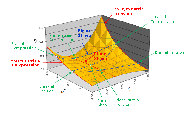
- FAILIP is an integer value that is used only with higher order or fully-integrated solid elements. It defines the number of failed integration points prior to solid element deletion.
- PTHICKFAIL parameter is a real parameter used for
shell elements. If PTHICKFAIL is blank or set to 0.0, the
value of PTHICKFAIL from the shell property is used. If
PTHICKFAIL > 0.0, any PTHICKFAIL
value defined in the shell properties are ignored and the value entered in
this failure model is used.
For values of PTHICKFAIL > 0.0, shell elements fail and are deleted when the ratio of through thickness failed integration points equals or exceeds PTHICKFAIL.
- The damage variable evolution is given by:The parameter N then allows you to change the shape of the damage evolution with plastic strain shape from linear (N = 1, set by default) to nonlinear (N ≠ 1) (Figure 2(a)). An increase of N also creates a delay of the stress softening effect (Figure 2(b)).
Figure 2. Effect of parameter N on the damage variable evolution and the stress softening effect 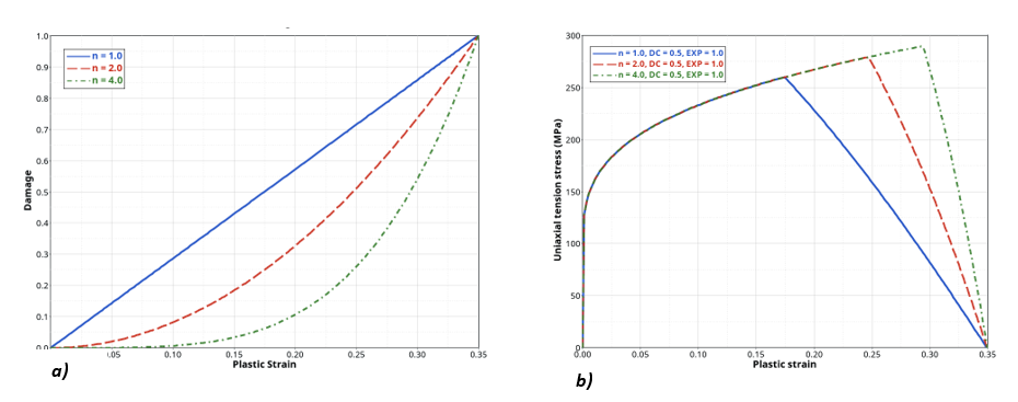
- The DCRIT parameter allows you to define a damage
variable trigger value for stress softening (Figure 3). By default,
DCRIT = 0.0, which means that damage variable always has
an effect on stress computation, generating a softening effect from the
beginning of the plasticity. However, you may want to delay this stress
softening effect to a higher value of damage variable (0 < D < 1) or
cut the effect of stress softening to obtain a fully failure criterion
approach where elements lose their load carrying capacity when damage
reaches the value 1.
Figure 3. Effect of parameter DCRIT on the stress softening effect 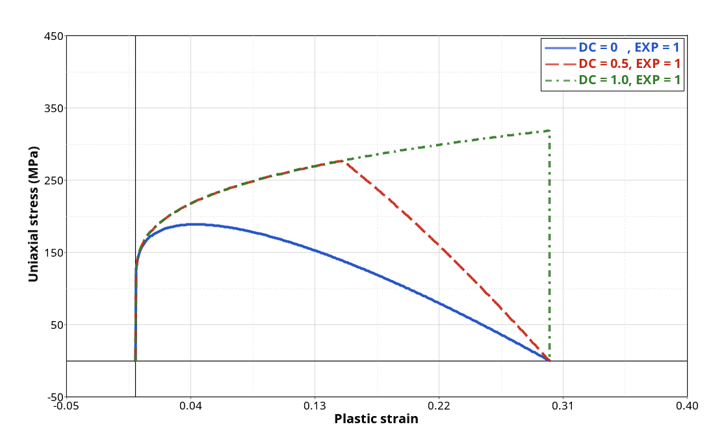
- Instead of using a constant value of DCRIT to
trigger stress softening, a necking control process can be used. This is
defined using the parameter INST_ID and/or
ECRIT. The definition of those parameters will imply
the computation of another variable evolution called instability variable
and denoted
:
The evolution of this instability variable is similar to the damage variable but represents the criterion to reach to trigger stress softening, implying the start of the strain localization and then necking especially observed at high stress triaxiality. When the criterion is reached ( = 1), the instant value taken by the damage variable D is saved in the value DCRIT, which becomes an element history variable and not a constant value. In this case, the DCRIT value defined in the input card is ignored.
ECRIT allows you to define a constant necking plastic strain. However, the necking plastic strain can be defined with a table INST_ID depending on stress triaxiality, Lode parameter and temperature. In this case, ECRIT becomes a scale factor for the instability plastic strain table. The instability plastic strain must be lower than failure plastic strain to have a visible effect (Figure 4).Figure 4. Necking plastic strain curve (blue) and failure plastic strain curve (red) 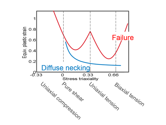
- There are two ways to define temperature dependency:
- The first way is by creating a 3-dimensions table in EPSF_ID, where the third dimension is the temperature dependency.
- The second way is to define the temperature dependency separately
from the third dimension of tables defined with
EPSF_ID and INST_ID. To do
so, a specific temperature dependency function can be introduced
with FCT_TEMP. In this case, the plastic strain
at failure and the plastic strain at necking are both multiplied by
the temperature dependent scale factor (denoted
):
In this case, the temperature dependency defined in EPSF and INST tables should be removed, else FCT_TEMP will be ignored.
- Even if the shape of the damage accumulation can be controlled with
parameter N, another non-linearity in stress softening
can be defined with the exponent EXP (Figure 5). This exponent can be constant if
EXP parameter is defined alone or can evolve with
element size if FCT_EXP is specified. If the function is
used, EXP_REF is the element reference size and
EXP becomes a scale factor. By default,
EXP is set to 1.0 leading to a linear decrease.
Figure 5. Effect of exponent parameter EXP on the stress softening shape 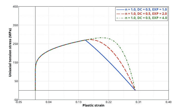
- Element size scaling can be
used to regularize the failure and ensure an almost constant fracture energy
dissipated with different mesh sizes is obtained. This element size
dependency is introduced by computing a size scale factor denoted
defined by the table
TAB_EL. The dependencies of these tables depend on
the value of the IREG flag:
- IREG = 1: the table defines the
evolution of the element size scaling factor with respect to initial
element size and strain rate
. In this case,
EL_REF is the reference element size
, and SR_REF1 is
the reference strain rate
. Note: If the first strain rate value in the table is negative, the logarithmic scale is assumed.
- IREG = 2: the table defines the evolution of the element size scaling factor with respect to initial element size and stress triaxiality . In this case, EL_REF is the reference element size , and SR_REF1 is ignored. A third dimension can be defined, introducing a dependency to Lode parameter .
In both cases, FSCALE_EL is a scale factor that quickly increases or decreases the values of the entire table. The element size scale factor thus computed is introduced in the damage variable evolution equation (and if defined, the instability variable evolution equation) as:Note: If IREG = 1 is used, the element size scaling can be turned off, if the stress triaxiality is lower than the boundary SHRF, or is higher than the boundary BIAXF. - IREG = 1: the table defines the
evolution of the element size scaling factor with respect to initial
element size and strain rate
. In this case,
EL_REF is the reference element size
, and SR_REF1 is
the reference strain rate
.
- A strain rate dependency can be also applied to the failure
criterion. This dependency can be introduced in two different ways:
- If FCT_SR ≠ 0, a tabulated
function of the strain rate dependency factor
is used. In this case, you must
define a function to describe the evolution of the strain rate
factor (denoted
) with the strain rate. You can also
input a reference strain rate SR_REF2 denoted
in the equation, and a scale factor. Using
the tabulated strain rate dependency, the damage variable
computation (and if defined, the instability variable evolution
equation) becomes:Note: If the first strain rate value in the table is negative, the logarithmic scale is assumed.
- If
, the Johnson-Cook strain rate
dependency is used and SR_REF2 becomes the
reference strain rate
. In this case, the plastic strain at
failure value is multiplied by the strain rate dependency factor
as:Where,
- Inviscid limit strain rate.
- Strain rate dependency parameter.
- Macaulay brackets, which consider only positive values.
If you are using a Johnson-Cook material law coupled to the /FAIL/TAB2 criterion, the Johnson-Cook parameters used for the constitutive law might not be the same for the failure criterion. The reference strain rate used in the presented equation is different from the one used for element size scaling when IREG = 1.
Important: The strain rate dependency applied to the failure criterion can only be used with material laws that are strain rate dependent. The strain rate used for the constitutive law (total strain rate, deviatoric strain rate or plastic strain rate), will be the same used for the failure criterion.
- If FCT_SR ≠ 0, a tabulated
function of the strain rate dependency factor
is used. In this case, you must
define a function to describe the evolution of the strain rate
factor (denoted
) with the strain rate. You can also
input a reference strain rate SR_REF2 denoted
in the equation, and a scale factor. Using
the tabulated strain rate dependency, the damage variable
computation (and if defined, the instability variable evolution
equation) becomes:
- The stress softening can be restricted to a given range of stress triaxiality. To do so, a damage limit value (lower than 1 for which the element has lost its load carrying capacity) evolving with stress triaxiality may be defined using the function FCT_DLIM. Values taken by this function must be taken between 0 and 1. A scale factor can be used to quickly increase or decrease the entire function values.
- If the non-local regularization is used (/NONLOCAL/MAT), the non-local plastic strain is used to compute the damage evolution (and the instability variable if used). In that case, if an element size scaling is defined through TAB_EL or an element size dependent exponent parameter function FCT_EXP is used, the maximum non-local length parameter LE_MAX is used instead of the initial element size.
- The fail_ID is used with /STATE/BRICK/FAIL and /INIBRI/FAIL. There is no default value. If the line is blank, no value will be output for failure model variables in the /INIBRI/FAIL (written in the .sta file with /STATE/BRICK/FAIL option).
- VOLFRAC is used for fully-integrated and higher order solids elements only. It represents the damaged volume fraction (that is, the sum of damaged integration points associated volumes) value to reach to trigger the element deletion.