RD-E: 4701 Splitting Tensile Test (Brazilian Test)
Using a splitting tensile test to calculate input for material LAW24.
Figure 1.
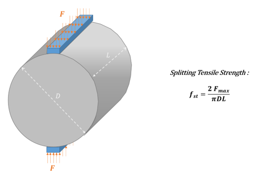
A splitting tensile test is also known as a Brazilian test. It is a
typical test used for concrete material characterization carried out using procedure
adhering to ASTM D3967, “Standard Test Method for Splitting Tensile Strength of
Intact Rock Core Specimens”. A load is applied to a concrete cylinder with its axis
normal to the loading direction. A tensile stress develops in the center. The force
is slowly increased until the specimen fails by an extension fracture along the
loading plane. Then the tensile strength is computed from this force of failure.
The splitting tensile test aims to evaluate failure limits. It is difficult to apply
uniaxial tension to a concrete specimen. Therefore, the tensile strength of the
concrete material is determined by indirect test methods such as a Split Cylinder
Test or even a Flexure Test. It should be noted that both methods give a higher
value of tensile strength than the uniaxial tensile strength. This will be explained
in the current example. This test will be modeled, and test results will be used for
numerical calibration of the material law.
Since this test is quasi-static, a concrete cylinder is crushed with slow velocity.
It is the standard test, to evaluate the tensile strength of concrete. This test
could be performed following IS:5816-1970.
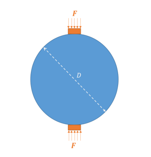
A cylinder of the concrete specimen is placed horizontally between the loading
surfaces of a compression testing machine (Figure 2). The compression load is applied
diametrically and uniformly along the length of the cylinder until the failure of
the cylinder along the vertical diameter. A uniform distribution of the pressure
load is created by using strips of plywood which are placed between the specimen and
loading plates of the testing machine. This also reduces the magnitude of the high
compressive stresses near the points of application of this load, concrete cylinders
split into two halves along the vertical plane due to indirect tensile stress
generated by Poisson's effect.Figure 2. Diametrically loaded concrete cylinder
Assuming the concrete specimen behaves as an elastic body, a uniform lateral tensile
stress acting along the vertical plane causes the failure of the specimen. This can
be calculated from the following formula for the splitting tensile strength:
Where,
Cylinder length
Diameter
Ultimate force that leads to failure causing the specimen to split into
two halves
The Radioss concrete material LAW24 is designed to work
with only a few mandatory parameters. The other parameters are optional. If the
optional parameters are not entered default values are calculated using typical
properties of concrete material.
The numerical implementation is based on work by Han & Chen. 1 It defines an Ottosen failure envelope. 2 It can be fully determined by providing 4 failure points
which are described with 5 parameters. The mandatory input is compression strength . The four other ones are optional parameters. They
are written as a ratio of compression strength which allows the following default
values that are typical for concrete:
Direct Tensile Strength:
Biaxial Compression Strength:
Confined Compression Strength (tri-axial test):
Confined pressure:
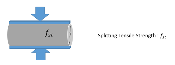
Splitting Tensile Test
If only splitting tensile test data is available, then all of the failure parameters are not available.Figure 3. Splitting Tensile test illustration
Experience provides that is related to loading force on the cylinder. This value is sometimes used as an
estimation of the direct tensile strength which is one of the input parameters. It can be
observed that .
Elastic theory enables to write:
Where,
Loading force
Cylinder diameter
Length
Position on the diameter
This formula is maximized at the center, where =0 to obtain:
The loading path direction and stress state in this test are different than a typical
uniaxial tensile test. The material in this test undergoes both compression and
tension. Compression is due to the loading force over the cylinder, and tension is
due to the Poisson effect.
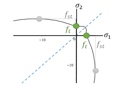
Another significant finding from this theoretical result is to observe that the
direct tensile strength is lower than splitting tensile strength (Figure 4). Figure 4. Splitting tensile strength versus direct tensile strength
on the failure envelope
Fusco suggested for conventional concrete buildings the relation but other authors found the relation . 4
Using the theoretical loading path from the elastic hypothesis with Han & Chen
failure surface and the values for concrete:
; ;
leads to the following estimation:
This estimation is of course dependent on the failure envelope which is shaped by all
5 parameters. Changing their values will change the
ratio.
Rigid Walls
Rigid walls are used to model the plywood used in the test to apply the load. Nodes
on the cylinder the width of the plywood are included as secondary nodes of the
rigid wall. A high friction value is set to prevent the concrete cylinder from
sliding.
Loading Pressure
A compressive load is created by applying displacements in opposite directions to
both rigid walls using the imposed displacement option /IMPDISP.
The imposed displacement uses a linear function large enough to split the cylinders
in half.
Solid Properties
qa =1e-20 and
qb =1e-20
Isolid = 24
IHKT = 2
All other property values use the default options
Material Data
Units: mm, ms, g, MPa
The concrete material data is:
Initial density = 0.0024
Concrete elasticity Young’s modulus
Poisson’s ratio
Concrete uniaxial compression strength from test
Concrete uniaxial tension strength is 0.05 so the ratio is defined as
All other parameters can be left as default in LAW24 because the default
values are representative of generic concrete materials.
Some measurement from splitting tensile test data:
Starting with the nominal values:
Tensile strength with
Biaxial Compression Strength:
by default.
Confined Compression Strength (tri-axial test):
by default
Confined pressure: by default
This leads to the following material card input file.
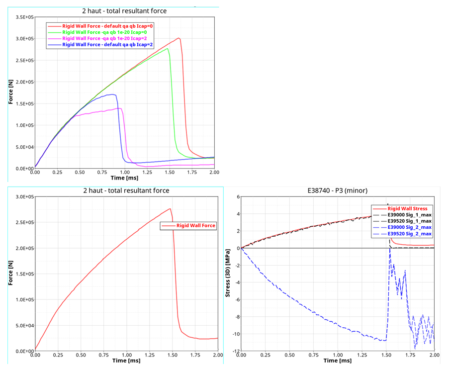
Results
The maximum force measured from the rigid wall is 275612 N which is close to the
maximum force from the test of 280100 N. The elastic theory equations at d=0 predict
that the principal stress P1 at the center of the cylinder should be 3.90 MPa. The
principal stress P2 at the center of the cylinder should be -11.7
MPa.
The stress of the center elements, Element ID 39000 and 39520, show that the results
match the analytical results of 3.96 MPa.Figure 5. Simulation rigid wall force and stress at some center
elements
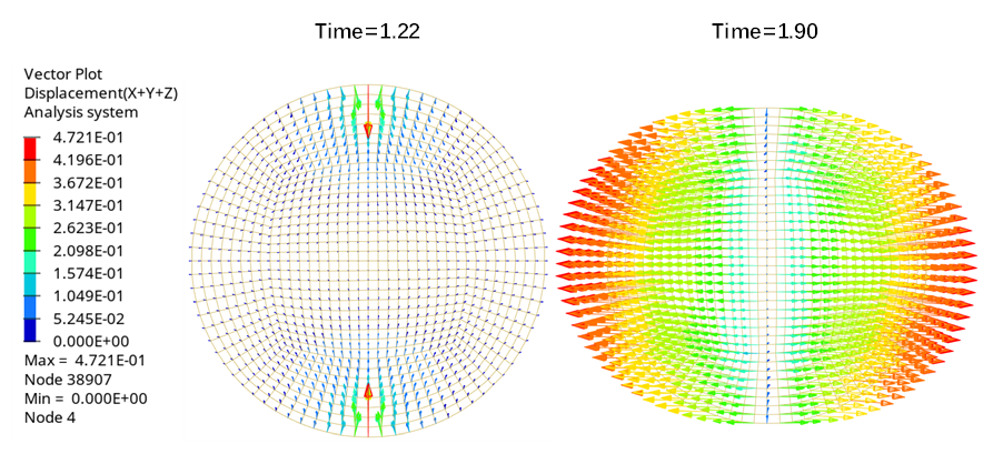
From the displacement plot, the Poisson's effect is shown at the top and bottom
elements. The center of the cylinder is under tensile loading until the cylinder is
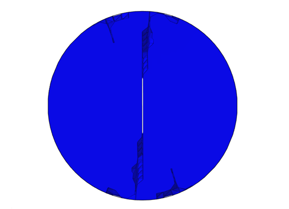
cracked.Figure 6. After the failure at T=1.90, the concrete has failed and
the displacement is horizontal Figure 7. Plot of principal values in the local cracking using
/ANIM/BRICK/DAM1
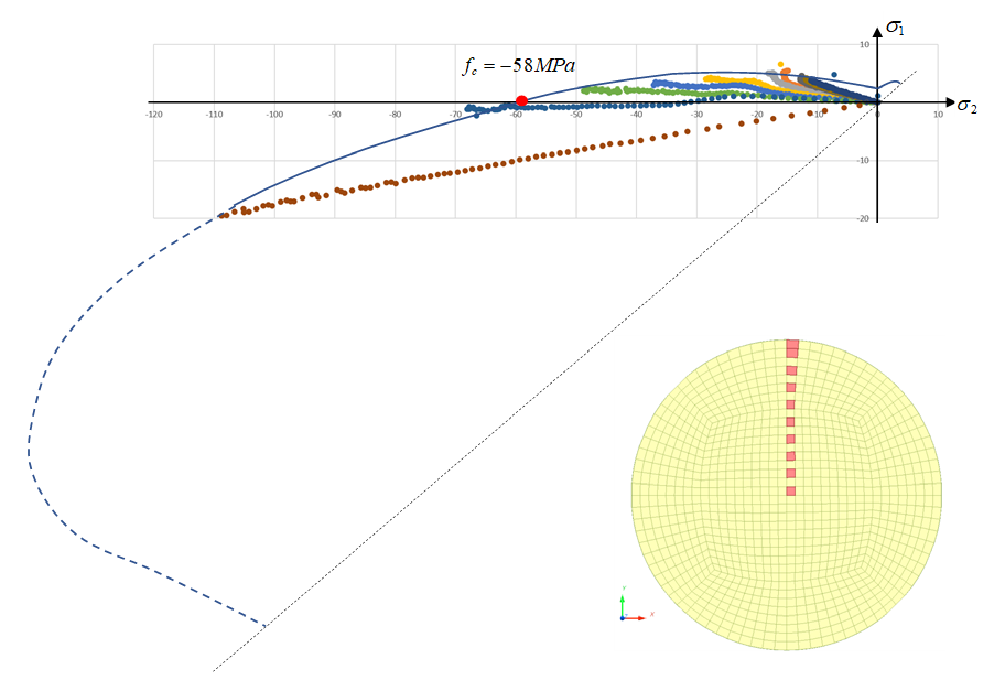
The numerical result is consistent with the theoretical solution. However, there is a
slight deviation when approaching the failure limit due to the crack opening and
damage in adjacent finite elements (nonlinearities). The next diagram shows the
principal stress of some elements from the simulation.Figure 8. Failure limit
Conclusion
The splitting tensile strength measured from the Brazilian test is bigger than the
tensile strength from a direct tensile test . Using LAW24 with mostly default values, the tensile
strength is about 0.71 times the splitting tensile strength . Only the maximum force from the splitting tensile test and from a cube compression test are needed as input to
LAW24.
From a splitting tensile test, the parameter in LAW24 could be determined.
Next, compare the experiment and simulation force and
strength.
1 D.J. Han, W.F. Chen “Plasticity model for concrete in Mechanics of
Materials”, North Holland
2 Ottosen N.S. “Nonlinear Finite Element Analysis of Concrete Structures”
Ris. National Laboratory DK 4000 Roskilde Denmark, May 1980
3 FUSCO, P.B. Concrete structures - Fundamentals of structural design.
McGraw-Hill, 1976, São Paulo.
4 A. Ghaffar, M. A. Chaudhry and M. Kamran Ali - A new Approach for
measurement of tensile strength of concrete - Journal of Research, Bahauddin
Zakariya University, Vol.16, No.1, June 2005, pp. 01-0