OS-T: 1365 NLSTAT Analysis of Solid Blocks in Contact
This tutorial demonstrates how to carry out nonlinear implicit small displacement analysis in OptiStruct, involving elasto-plastic materials, contact and continuing the nonlinear solution sequence from a preceding nonlinear loadcase.
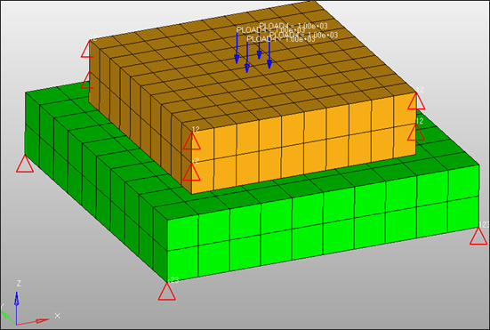
Figure 1 illustrates the structural model used for this tutorial, which is two square solid blocks made of elasto-plastic steel material. The dimensions of the blocks and the material parameters are outlined below Figure 1.
- Units
- Length: mm; Time: s; Mass: Mgg; (Force: N; Stress: MPa)
- Top block
- 72 mm x 72 mm
- Bottom block
- 100 mm x 100 mm
- Thickness of blocks
- 20. mm
- Material
- Steel, Elasto-plastic
- Imposed pressure
- 1000.0 MPa, applied at the center of top block
Launch HyperMesh and Set the OptiStruct User Profile
-
Launch HyperMesh.
The User Profile dialog opens.
-
Select OptiStruct and click
OK.
This loads the user profile. It includes the appropriate template, macro menu, and import reader, paring down the functionality of HyperMesh to what is relevant for generating models for OptiStruct.
Open the Model
- Click .
- Select the nlstat.hm file you saved to your working directory.
-
Click Open.
The nlstat.hm database is loaded into the current HyperMesh session, replacing any existing data.
Set Up the Model
Create Elasto-plastic Material
First, the stress versus plastic strain curve for the material needs to be defined.
-
In the Model Browser, right-click and select .
A new Curve editor window opens.
- For Name, enter stress-strain.
-
In the pop-up window, enter the following X and Y values.
Figure 2. 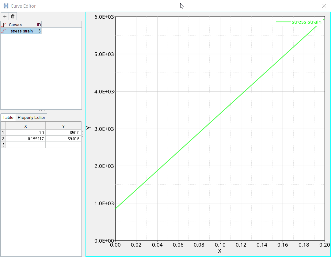
- Close the window.
- In the Model Browser, under Curve select stress-strain.
- Click Color and select a color from the color palette.
- For Card Image, select TABLES1 from the drop-down menu.
-
In the Model Browser, click the material
steel.
The Entity Editor opens.
- Click on the checkbox next to MATS1 to define the elastic-plastic material for NLSTAT analysis.
- For TID, click .
- In the Select Curves dialog, select the stress_strain curve and click OK.
-
Input the values, as shown below.
TYPSTRN of 1 signifies specifying stress (Y) versus plastic strain (X).
Figure 3. 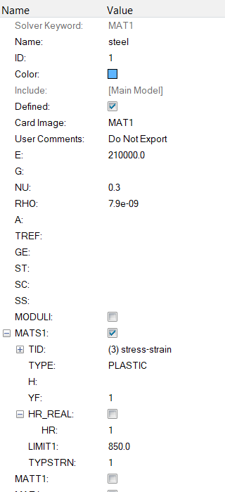
Define Contact between the Blocks
- In the Model Browser, right-click and select .
- For Name, enter top.
- For Card Image, select SET_ELEM from the drop-down menu.
- Leave the Set Type switch set to non-ordered type.
- For Entity IDs, click .
-
In the Select Properties dialog, select the top solid
block Solid1 and click OK.
Figure 4. 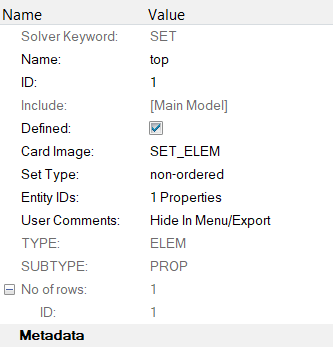
- Similarly create another set named bottom.
- Repeat steps 3 through 6 for bottom block select the bottom solid Solid2.
- In the Model Browser, right-click and select .
- For Name, enter SOLID_CONTACT.
- Click Color and select a color from the color palette.
- For Card Image, select CONTACT from the drop-down menu.
- For Main Entity IDs and select Set from the extended selection menu.
- Click the yellow Set panel and select the bottom block bottom in the pop-up window and click OK.
- Similarly, for Secondary Entity IDs, select the top set.
- For TYPE, select SLIDE from the drop-down menu.
-
For MORIENT, select NORM from the drop-down menu.
Figure 5. 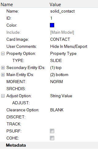
Create NLPARM Load Step Input
- In the Model Browser, right-click and select .
- For Name, enter NLPARM.
-
Enter the values as shown below:
Figure 6. 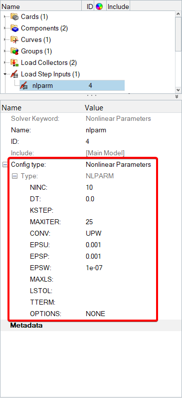
Create the 1st Nonlinear Load Step
- In the Model Browser, right-click and select .
- For Name, enter loading.
- Click Analysis type and select Nonlinear static from the drop-down menu.
- For SPC, click .
- From the Select Loadcol dialog, select SPC from the list of load collectors and click OK.
- For LOAD, click .
- From the Select Loadcol dialog, select pressure from the list of load collectors and click OK.
- For NLPARM, click .
-
From the Select load step inputs dialog, select
nlparm from the list of load step inputs and click
OK.
Figure 7. 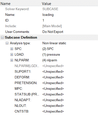
Create the 2nd Nonlinear Load Step
- For Name, enter unload.
- The Analysis type should, again, be set to Nonlinear static from the drop-down menu.
- For SPC, select SPC from the list of load collectors.
-
For NLPARM, select nlparm from the list of load step
inputs.
Checkpoint: The unloading subcase (unload) does not contain the pressure load applied during the loading subcase (loading).
Figure 8. 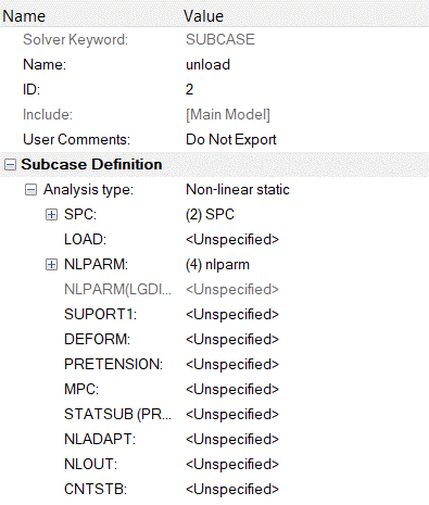
Define Output Control Parameters
- From the Analysis page, select control cards.
- Click on GLOBAL_OUTPUT_REQUEST.
- Below CONTF, DISPLACEMENT, STRAIN and STRESS, set Option to Yes.
- Under STRAIN, set TYPE(1) to PLASTIC.
- Click return twice to go to the main menu.
Submit the Job
-
From the Analysis page, click the OptiStruct
panel.
Figure 9. Accessing the OptiStruct Panel 
- Click save as.
-
In the Save As dialog, specify location to write the
OptiStruct model file and enter
nlstat_complete for filename.
For OptiStruct input decks, .fem is the recommended extension.
-
Click Save.
The input file field displays the filename and location specified in the Save As dialog.
- Set the export options toggle to all.
- Set the run options toggle to analysis.
- Set the memory options toggle to memory default.
- Click OptiStruct to launch the OptiStruct job.
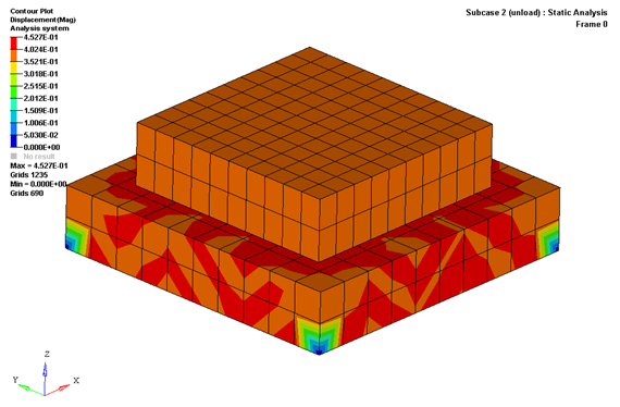
View the Results
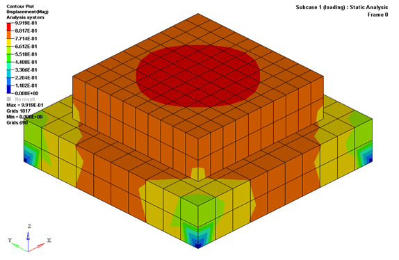
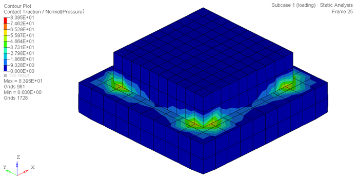
Next, change the subcase to the 2nd that is unloading subcase and plot the displacement contour to see the change in displacements in the blocks subject to unloading.