
OS-T: 1370 Complex Eigenvalue Analysis of a Reduced Brake System
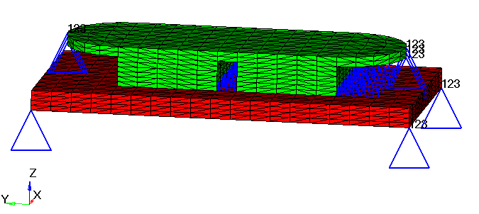
In this tutorial, a modal complex eigenvalue analysis is performed on a simplified brake system to determine whether the friction effects can cause any squeal noise (unstable modes).
Launch HyperMesh and Set the OptiStruct User Profile
-
Launch HyperMesh.
The User Profile dialog opens.
-
Select OptiStruct and click
OK.
This loads the user profile. It includes the appropriate template, macro menu, and import reader, paring down the functionality of HyperMesh to what is relevant for generating models for OptiStruct.
Import the Model
-
Click .
An Import tab is added to your tab menu.
- For the File type, select OptiStruct.
-
Select the Files icon
 .
A Select OptiStruct file browser opens.
.
A Select OptiStruct file browser opens. - Select the brake.fem file you saved to your working directory.
- Click Open.
- Click Import, then click Close to close the Import tab.
Set Up the Model
Create EIGRL and EIGC Cards
- In the Model Browser, right-click and select .
- For Name, enter eigrl.
- For Config type, select Real Eigen Value Extraction.
- For Type, select EIGRL from the drop-down menu.
-
For ND, enter 20.
20 real modes are required to produce the reduced space for complex eigenvalue analysis.
Figure 2. 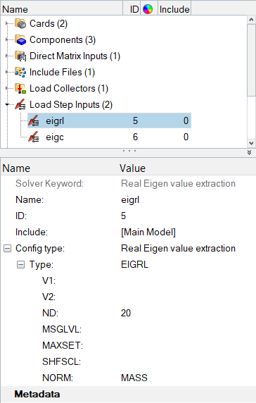
- Create another load step input named eigc.
- For Config type, select Complex eigen value extraction.
- For Type, verify the default EIGC is selected.
-
For NORM, select MAX.
MAX option is used to normalize the eigenvectors.
- For ND0 OPTIONS, select User Defined from the drop-down menu.
-
For ND0, enter 12.
The desired number of roots to be extracted is 12.
Retrieve Friction Data and Define Analysis Parameters
- Go to the Analysis page, then click control cards.
- Click INCLUDE_BULK.
- Input the name of the include file, DMIG.pch.
- Click return to go back to control cards.
- Click K2PP.
- In K2PP panel, set number_of_k2pps= 1.
-
In the field of K2PP=, enter KF.
KF is the name of the DMIG Data Entry.
- Click return and back to control cards.
- Click PARAM.
- Check the small box in front of parameter G.
- Click [G_V1] and input 0.2 as the structural damping coefficient.
- Check the small box in front of parameter FRIC.
-
Click [VALUE] and input
0.05.
Friction factor 0.05 is used to scale the friction coefficient from DMIG Data Entry.
- Click return twice and go back to the Analysis page.
Define a Load Step for Modal Complex Eigenvalue Analysis
- In the Model Browser, right-click and select .
- For Name, enter complex_eigen.
- Click Analysis type and select Complex eigen (modal) from the drop-down menu.
- For SPC, click .
- In the Select Loadcol dialog, select SPC from the list of load collectors and click OK.
- For CMETHOD, click .
- In the Select Load step inputs dialog, select eigc from the list of load step inputs and click OK.
- For METHOD(STRUCT), click .
- In the Select Load step inputs dialog, select eigrl from the list of load step inputs and click OK.
Submit the Job
-
From the Analysis page, click the OptiStruct
panel.
Figure 3. Accessing the OptiStruct Panel 
- Click save as.
-
In the Save As dialog, specify location to write the
OptiStruct model file and enter
brake_complex for filename.
For OptiStruct input decks, .fem is the recommended extension.
-
Click Save.
The input file field displays the filename and location specified in the Save As dialog.
- Set the export options toggle to all.
- Set the run options toggle to analysis.
- Set the memory options toggle to memory default.
- Click OptiStruct to launch the OptiStruct job.
View the Results
-
Load the brake_complex.out file in a text editor.
The complex modes contain the imaginary part, which represents the cyclic frequency, and the real part which represents the damping of the mode. If the real part is negative, then the mode is said to be stable. (For complex eigenvalue analysis, such unstable modes are also indicated by an asterisk next to the mode number). If the real part is positive, then the mode is unstable. The eigenvalues of the complex modes are shown below:
Figure 4. 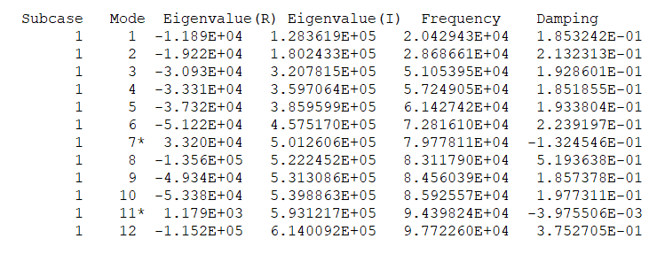
It can be observed that the 7th and 11th modes are unstable, while all the other modes are stable.
The friction coefficient parameter can be reduced by setting the PARAM,FRIC factor from a value of 0.05 to 0.01, and all roots become stable. It illustrates that there is a stability threshold between the friction factor 0.05 and 0.01. It can be determined by resetting the scale factor of PARAM, FRIC and rerunning the model till the damping value of this mode approaches zero.
- Load the brake_complex.h3d file into HyperView to review complex eigenvectors.