OS-T: 1392 Node-to-Surface versus Surface-to-Surface
Contact
This tutorial demonstrates how to set up contact between two parts and the impact of
using choosing node-to-surface (N2S) versus surface-to-surface (S2S). In addition, this
tutorial covers how to review the internally created CGAPG elements in case of N2S, and the
nodes in contact in case of S2S.
Before you begin, copy the file(s) used in this tutorial to your
working directory.
The model consists of two cubes in contact and enforced displacement on the top
compressing the structure.Figure 1. Illustration of the Model
Launch HyperMesh and Set the OptiStruct User Profile
Launch HyperMesh.
The User Profile dialog opens.
Select OptiStruct and click
OK.
This loads the user profile. It includes the appropriate template, macro
menu, and import reader, paring down the functionality of HyperMesh to what is relevant for generating models for
OptiStruct.
Import the Model
Click File > Import > Solver Deck.
An Import tab is added to your tab menu.
For the File type, select OptiStruct.
Select the Files icon .
A Select OptiStruct file browser
opens.
Select the blocks_contact.fem file you saved
to your working directory.
Click Open.
Click Import, then click Close to
close the Import tab.
Set Up the Model
Create Set Segments
The imported model already contains the material, the property, the boundary conditions and
the loadstep. In this step, the set segments and the interface are created.
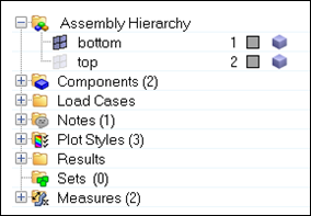
In the Model Browser, right-click and select
Expand All.
Right-click in the Model Browser and select Create > Set Segment to create a set segment.
Figure 2. Create a Set Segment from the Model Browser
For Name, enter bottom.
In the Model Browser, right-click on the component
bottom under Component and select Isolate
Only.
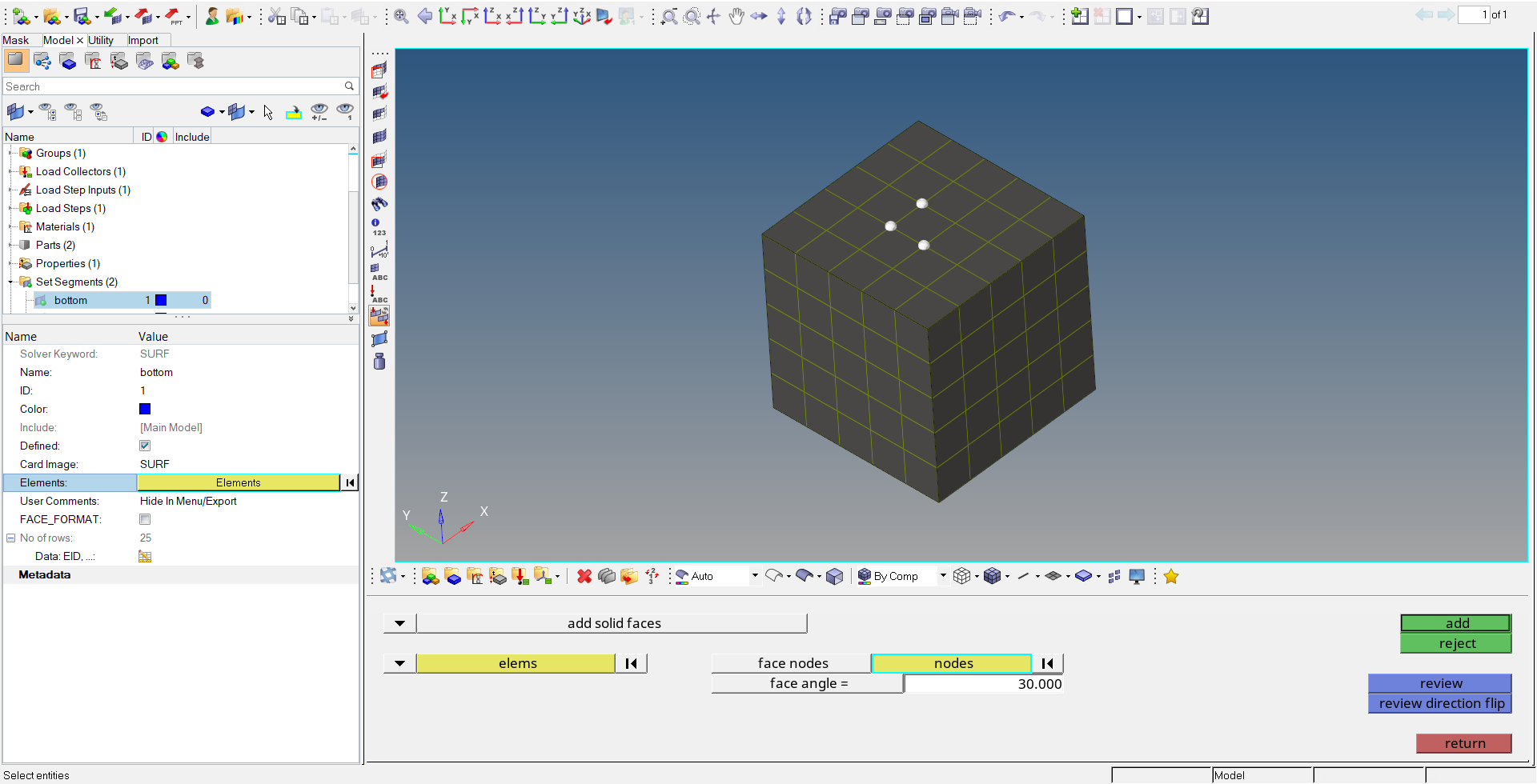
To add elements and their faces to the surface, select the
bottom set segment in the Model Browser and click on 0 Elements in
the Entity State Browser.
Click Element to select elements from the panel. Switch
the selector to Solid faces, as this contact surface will
be on solid elements.
Switch the second drop-down menu to elems.
Click elements and click
displayed to select all elements from the bottom part
of the structure.
Select three nodes on the surface that are in contact with the top part. Make sure the three nodes are all part of one element.
Click return to finish.
Repeat steps 3 through 9 to create the top part.
Figure 3. Add a Set Segment
Create the Contact Interface
After defining the two contact surfaces using set segments, you need to define that they
are in contact and with which properties. A contact interface needs to be
defined.
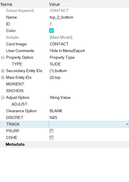
In the Model Browser, right-click and select Create > Contact.
For Name, enter top_to_bottom.
In the Model Browser, select the newly created
Contact to modify the properties of the
contact.
For TYPE, select SLIDE.
This will result in a frictionless contact.
To select the secondary surface, click on the field next to Secondary Entity
IDs.
The secondary surface should be the finer side, in this case the bottom (refer
to the User Guide).
Select the top for Main Entity IDs.
For DISCRET, select N2S.
Retain the default values in the remaining fields, for now.
Click anywhere in the Model Browser to apply these
changes.
Figure 4. Define the Contact interface
Create Output Requests
In the final step of model preparation, you want to request contact related output, CONTF;
which causes Contact Force, Contact Deformation, Contact Status and Contact Traction to
be output. Also, CONTPRM,CONTGAP, CONTPRM,CONTGRID
and GAPPRM,HMGAPST are used to review the created contact
elements.
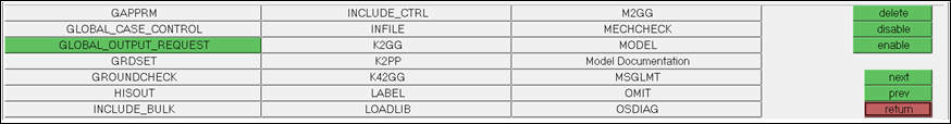
From the main menu, select Setup > Create > Control Cards.
Select GLOBAL_OUTPUT_REQUEST and
CONTF.
Figure 5. Set up a Global Output Request
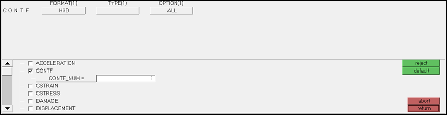
In the next panel, select the settings to request contact related output, as shown below.
Figure 6. Request Contact Related Output
Click return to complete the card definition.
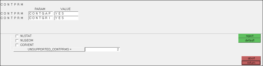
Repeat the steps above to create the CONTGAP and CONTGRID cards, as seen in
Figure 7.
They are available under the CONTPRM control card.
Select UNSUPPORTED_CONTPRMS and enter
2.
Then create the following cards below.
CONTPRM,CONTGAP,YES (outputs the internally created
CGAPG for N2S contact)
CONTPRM,CONTGRID,YES (outputs a set containing the
grids in S2S contact)
Click return.
Figure 7. Define CONTPRM cards CONTGAP and CONTGRID
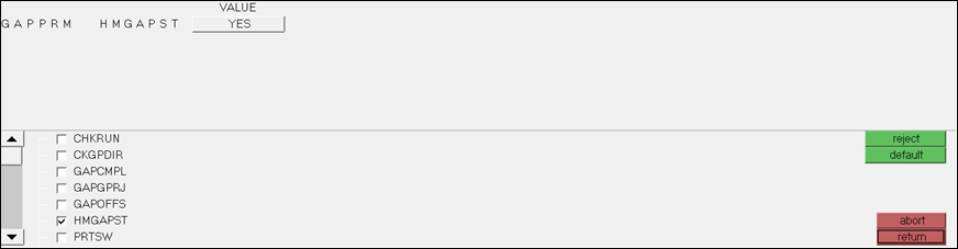
Click Next to locate the GAPPRM control card and click
HMGAPST.
Set the VALUE to YES.
Outputs the open/closed status of the CGAPG elements.Figure 8. Define GAPPRM card HMGAPST
Submit the Job
From the Analysis page, click the OptiStruct
panel.
Figure 9. Accessing the OptiStruct Panel
Click save as.
In the Save As dialog, specify location to write the
OptiStruct model file and enter
Contact_N2S for filename.
For OptiStruct input decks,
.fem is the recommended extension.
Click Save.
The input file field displays the filename and location specified in the
Save As dialog.
Set the export options toggle to all.
Set the run options toggle to analysis.
Set the memory options toggle to memory default.
Click OptiStruct to launch
the OptiStruct job.
If the job is successful, new results files
should be in the directory where the Contact_N2S.fem was written. The Contact_N2S.out file is a good place to look for error messages that could help
debug the input deck if any errors are present.
Submit a Job for S2S
In the Model Browser, select the
top_to_bottom card under Group.
Set DISCRET to S2S.
Repeat the steps in Submit the Job, with
the new file name Contact_S2S.fem.
View the Results
Displacements, Element Stresses, Contact Force, Contact
Deformation, Contact Status and Contact Traction are calculated and can be plotted
using the Contour panel in HyperView. Only compare the Contact Traction between the N2S and the S2S
run.
Compare the Contact Traction
When the message Process completed successfully is received in
the command window, click HyperView.
HyperView is launched and the results are loaded
for the S2S run. A message window appears to verify that the model and result
files are loading into HyperView.
Click Close to close the message window, if one
appears.
Select the page window layout icon to split the page into two
windows.
Load the other model in the new window by clicking and selecting
contact_N2S.h3d.
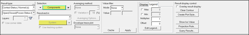
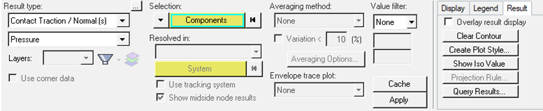
Click the Contour toolbar icon in one of the two windows.
For Result type, select Contact
Traction/Normal(s).
Click Apply.
Figure 10. Contour Plot Panel in HyperView
In the Model Browser, unselect the
top part of the structure.
Only the results on the contact surface are visible.Figure 11. Isolate the Bottom Part of the Structure in HyperView
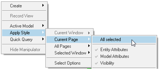
Right-click in the window that shows the contour and select Apply Style > Current Page > All selected to view the same results for both models.
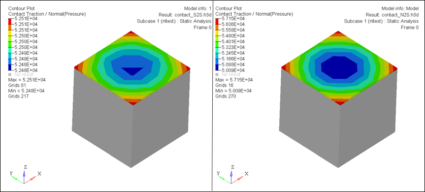
A contour plot of normal contact traction shows for both runs. The
traction for the S2S run is much more uniform than for N2S by comparing the
maximum and minimum values.Figure 12. Apply the Setup in One Window to the Rest of the Page Figure 13. Contour of the Normal Contact Traction for S2S on the Left and N2S on
the Right
Review the Internally Created CGAPC Elements
After viewing the contact traction in HyperView, check the
internally created contact elements for the N2S.
Repeat
Steps 1.1
through 1.4.
Select the Contact_N2S.fem file, located in the folder
selected in
Step
1.4.
Import the internally created CGAPG elements by importing the file
contact_N2S.contgap.fem.
Right-click on the component Gaps from CONTACT1 in the
Model Browser to review the gap elements.
Select isolate only to visualize the elements
better.
Click to turn
on the element tags.
Click File > Run > Command File to create element sets to identify the open/closed status of the
elements at the end of the run.
Select the file contact_N2S.HM.gapstat.tcl.
Run a command file in HyperMesh to create sets
containing open and closed gaps.
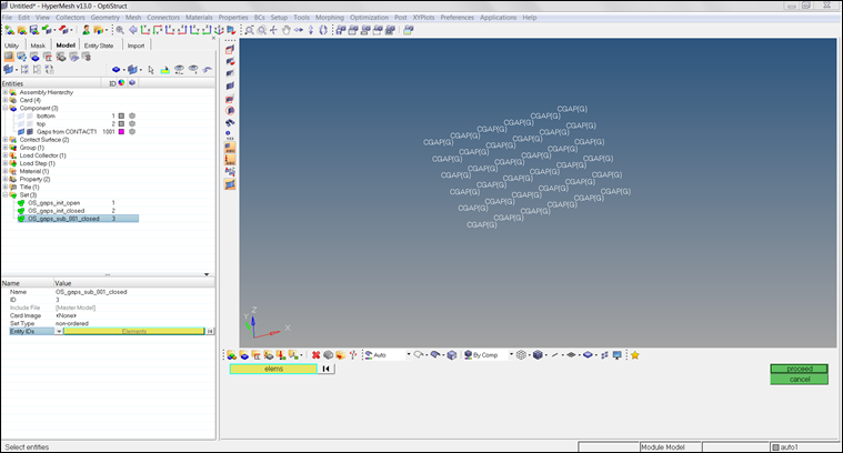
To see which gaps are closed or open at the end of the simulation, review the
element sets that were created. Review the set
OS_gaps_sub_001_closed by selecting it in the
Model Browser and clicking on the field next to Entity
IDs in the Entity State Browser.
This shows that all gaps are closed, as it contains all elements. If
there were some open gaps, another set
OS_gaps_sub_001_open would have been created, as
well.Figure 14. Review the Closed Gaps at the End of the Analysis
Review the Grids
The contact for S2S contact is different from N2S in the sense that no CGAPG elements are
created internally. This means the process in Step 8 cannot be applied to S2S contacts.
However, you can review the main and secondary grids that are being used in the S2S
contact, to ensure that the contact has been established in the correct
manner.
Repeat Steps
1.1 through
1.4.
Select the Contact_S2S.fem file, located in the folder
selected in
Step
1.4.
Import the grid set that show the grids where S2S contact has been established
by importing the file contact_S2S.contgrid.fem.
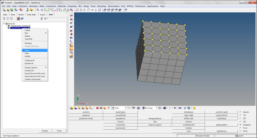
Right-click on the component bottom in the Model Browser and select isolate only to
review the grids.
Select Tools > Set Browser.
The Set Browser opens.
In the Set Browser, right-click on the set
^SecondGrids_Contact_#1 and select
Show.
Contact has been established on the entire surface as expected.Figure 15. Review the Secondary Nodes of the S2S Contact
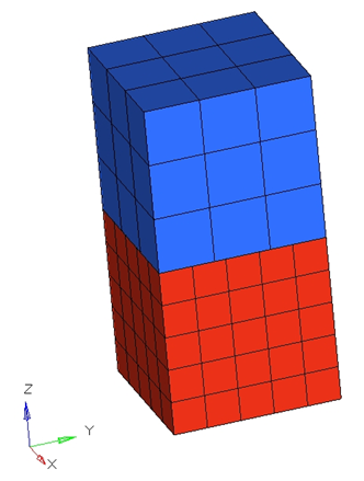
The contact status for both N2S and S2S can also be reviewed in HyperView, if the model contained the contact result
output request CONTF. To view this, repeat the steps in Compare the Contact Traction while choosing Contact Status/Normal(s) as the contour
plot.
Figure 16. Review the Contact Status in HyperView as
a Contour Plot

 .
A Select OptiStruct file browser opens.
.
A Select OptiStruct file browser opens.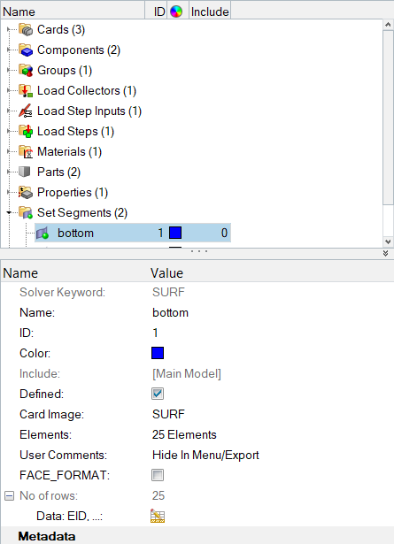

 to split the page into two
windows.
to split the page into two
windows.
 and selecting
contact_N2S.h3d.
and selecting
contact_N2S.h3d.
 in one of the two windows.
 to turn
on the element tags.
to turn
on the element tags.