OS-T: 1393 Basics of Contact Properties and Debugging
This tutorial demonstrates the effect of using contact stabilization, clearance, and adjust.
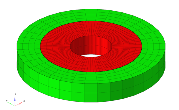
The model consists of two circular parts where the inner one is heated and the outer one cooled down, leading to contact between the two.
- Launch HyperMesh and import the model
- Definition of contact property with friction
- Run the model to encounter convergence issues
- Overcome convergence issue with contact stabilization
- Definition of contact clearance and adjust
- Comparison of the results in HyperView
Launch HyperMesh and Set the OptiStruct User Profile
-
Launch HyperMesh.
The User Profile dialog opens.
-
Select OptiStruct and click
OK.
This loads the user profile. It includes the appropriate template, macro menu, and import reader, paring down the functionality of HyperMesh to what is relevant for generating models for OptiStruct.
Import the Model
-
Click .
An Import tab is added to your tab menu.
- For the File type, select OptiStruct.
-
Select the Files icon
 .
A Select OptiStruct file browser opens.
.
A Select OptiStruct file browser opens. - Select the contact_S2S.fem file you saved to your working directory.
- Click Open.
- Click Import, then click Close to close the Import tab.
Set Up the Model
Create a PCONT Property
The base model already contains the material, property, boundary conditions and the loadstep definitions. Contact surfaces and the contact interface has also been defined.
A PCONT property is created to define friction, which will be referenced to the already created contact interface.
- In the Model Browser, right-click and select Expand All.
- Right-click on the Model Browser, and select to create a PCONT property.
- For Name, enter cont_prop.
- Click the drop-down menu next to Card Image and select PCONT.
-
In the MU1 field, specify a value of 0.2 for the
coefficient of static friction.
Figure 2. Contact Property Definition 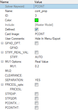
- In the Model Browser, select the interface contact_interface.
- Click the drop-down menu next to Property option and select Property Id.
- For PID, select cont_prop property.
Submit the Job
-
From the Analysis page, enter the OptiStruct
panel.
Figure 3. Accessing the OptiStruct Panel 
-
Click save as following the input file field.
The Save As dialog opens.
-
Select the directory where you would like to write the OptiStruct model file and enter the name for the model,
contact_S2S.fem, in the File name field.
For OptiStruct input files, .fem is the recommended extension.
-
Click Save.
The name and location of the contact_S2S.fem file displays in the input file field.
- Set the export options toggle to all.
- Set the run options toggle to analysis.
- Set the memory options toggle to memory default.
-
Click OptiStruct. This
launches the OptiStruct job.
If the job is successful, the new results files will appear in the directory where the input file was saved. Look in the contact_S2S.out file for error messages that could help debug the input deck, if any errors are present.
It can be noted that this model will encounter convergence issues and the job errors out. In the upcoming sections, different contact settings will be demonstrated to help the model achieve convergence.
Add Contact Stabilization
- Click .
- Select PARAM and check the box next to EXPERTNL.
-
Select CNTSTB to activate contact stabilization.
Note: Contact stabilization can also be activated through the CNTSTB Bulk Data Entry, which can be referenced in the subcase. This method provides more options to define contact stabilization.
-
Repeat Submit the Job, with the new file name
contact_CNTSTB.fem.
Figure 4. Creating PARAM,EXPERTNL,CNTSTB 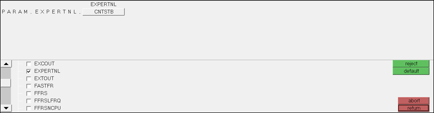
Note: The model converges successfully in the presence of contact stabilization.
Add Clearance
- In the Model Browser, select the cont_prop property.
-
In the Entity Editor, click on the field next to
CLEARANCE and enter the value 0.1.
Clearance will internally set the gap between the surfaces to the real value chosen, irrespective of the actual position of the grids, if grids are not moved to achieve this.
Figure 5. Contact Property Definition through PCONT 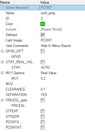
- Repeat Submit the Job, with the new file name contact_clearance.fem.
Add AUTO Adjust
- In the Model Browser, select the property cont_prop.
- Click on the field next to CLEARANCE and remove the previously specified value of 0.1.
- In the Model Browser, select the interface contact_interface.
-
Click on the field next to ADJUST and select AUTO.
Figure 6. Definition of ADJUST in the Contact Interface 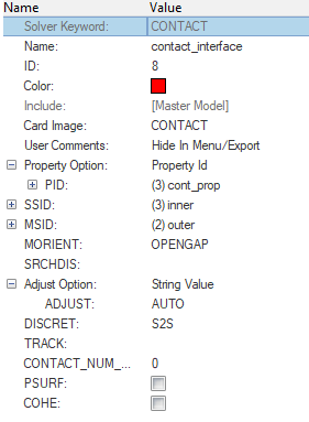
Apply Surface Smoothing
View the Results
Displacements, Element Stresses, Contact Force, Contact Deformation, Contact Status and Contact Traction are calculated and can be plotted using the Contour panel in HyperView.
Compare the Contact Traction
- Launch HyperView.
-
Select the page window layout icon
 to split the page into 3 windows.
-
Click
 to load the first model in one
of the window.
to load the first model in one
of the window.
- Select contact_CNTSTB.h3d for model and results.
- Click Apply.
- Do the same in the other two windows for contact_clearance.h3d and contact_adjust.h3d.
-
Click the Contour toolbar icon
 in one of the three windows.
- For Result type, select Contact Traction/Normal(s).
-
Click Apply.
Figure 7. Contour Plot Panel in HyperView 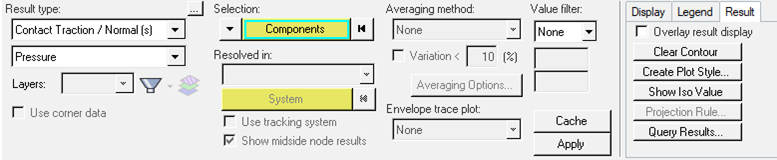
-
In the Entity Editor, unselect the
outer part of the structure.
Only the results on the contact surface will be visible.
-
Right-click in the window that shows the contour and select to view the same results for all models.
Figure 8. Apply the Setup in One Window to the Rest of the Page 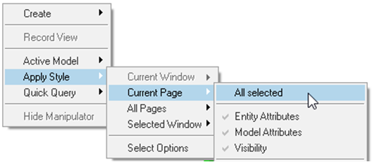
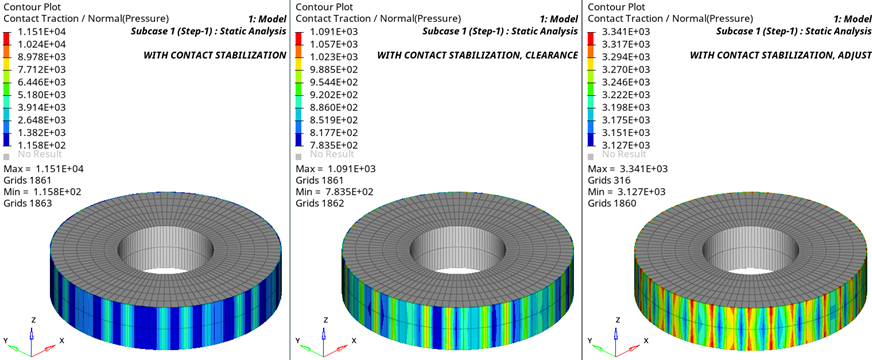
- A contour plot of normal contact traction shows for both runs.The traction for the models with clearance and adjust are more uniform than they are for the model with stabilization only. In addition, the peaks are much lower for these three models. In case of adjust, the gap is closed initially, leaving less room for stress free thermal expansion compared to the other cases. Hence, the contact traction is higher in this case adjust compared to the results with clearance.
Figure 9. Normal Contact Traction Contour for the Three Different Runs