
Reference: Marker
Model ElementA Reference_Marker defines an orthonormal, right-handed coordinate system and reference frame in MotionSolve. A Reference_Marker must belong to a body. The body can be any type: rigid, flexible, or point.
Description
The Newtonian reference frame (Ground) is considered to be a special case of a rigid body.
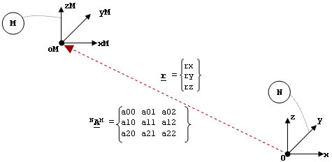
In the image above, N represents the Newtonian reference frame and coordinate system. It consists of a global origin O and three right-handed, mutually perpendicular directions denoted as OX, OY, and OZ.
M represents another coordinate system of interest. The origin of M is denoted by oM, and the axes of M are denoted as xM, yM, and zM. For this example, assume M is fixed with respect to N.
To define M, the measure numbers of the vector O-oM in the coordinate system N are needed. This is denoted as r in the image.
The rotation matrix that converts from the xM-yM-zM basis to the x-y-z basis is needed. This is denoted as NAM in the image.
- The vector r.
- The matrix NAM.
- The body to which it belongs.
- Defining reference coordinate systems (LPRF) for rigid bodies, flexible bodies, and point masses.
- Specifying the connections in constraint elements.
- Specifying the connections in force elements.
- Defining reference coordinate systems for Reference_Curve, Reference_Surface, and Post_Graphic.
- Defining output channels for measurement of displacements, velocities, and accelerations.
The Reference_Marker with id = 0 has special significance. In all MotionSolve expressions, it is used to denote the global coordinate system.
The attribute node_id is optional. It is used only for flexible bodies.
Format
<Reference_Marker
       id                    = "integer"
     [ label                 = "string" ]
       body_id               = "integer"
     [ body_type             = {"RIGIDBODY" | "FLEXBODY" | "POINTBODY"} ]
     [ rm_id                 = "integer" ]
     [ node_id               = "integer" ]
{
       pos_x                 = "real"
       pos_y                 = "real"
       pos_z                 = "real"
 [{
       a00                   = "real"
       a10                   = "real"
       a20                   = "real"
       a01                   = "real"
       a11                   = "real"
       a21                   = "real"
       a02                   = "real"
       a12                   = "real"
       a22                   = "real"
    |
       psi                   = "real"
       theta                 = "real"
       phi                   = "real"
    |
       yaw                   = "real"
       pitch                 = "real"
       roll                  = "real"
    |
       e0                    = "real"
       e1                    = "real"
       e2                    = "real"
       e3                    = "real"
 }]
}
|
{
      usrsub_param_string    = "USER(..,..)"
      usrsub_fnc_name        = "valid fnc name"
      usr_dll_name           = "valid dll name"
 |
      usrsub_param_string    = "USER(..,..)"
      usrsub_fnc_name        = "valid fnc name"
      interpreter            = "string
      script_name            = "valid script name"
}
/>
Attributes
- id
- Element identification number (integer>0). This number is unique to all Reference_Marker elements.
- label
- The name of the Reference_Marker element.
- body_id
- ID of the body to which marker belongs. The body may be Ground, a rigid body, a point mass, or a flexible body.
- body_type
-
Specifies whether the body is of type RIGIDBODY, FLEXBODY or POINTBODY
This parameter is optional. The default type is RIGIDBODY.
- rm_id
-
An optional attribute that specifies the Reference_Marker ID. If specified, the position and orientation of the marker is assumed to be with respect to the reference marker.
The default ID is 0 which refers to the global reference frame.
- node_id
- An optional attribute used only for flexible bodies.
- pos_x, pos_y, pos_z
- The x, y, z coordinates of the marker origin specified in terms of the global frame. pos_x defines the x-coordinate of the origin, pos_y defines the y-coordinate of the origin, and pos_z defines the z-coordinate of the origin.
- a00 a01 a02
- a10 a11 a12
- a20 a21 a22
- Elements of the transformation matrix defining the orientation of the Reference_Marker with respect to the global frame.
- psi
- In radians, the rotation around the original z-axis.
- theta
- In radians, the rotation around the new x-axis after Psi has been applied.
- phi
- In radians, the rotation around the new z-axis after Theta has been applied.
- yaw
- In radians, the rotation around the original z-axis of the marker.
- pitch
- In radians, the rotation about the new location of the y-axis of the marker after yaw has been applied.
- roll
- In radians, the rotation about the new location of the x-axis after pitch has been applied.
- e0, e1, e2, e3
- Euler parameters that describe the rotation.
- usrsub_param_string
- The list of parameters that are passed from the data file to the user defined subroutine.
- usrsub_fnc_name
- Specifies an alternative name for the user subroutine MARKER_READ.
- usrsub_dll_name
- Specifies the path and name of the DLL or shared library containing the user subroutine. MotionSolve uses this information to load the user subroutine in the DLL at run time.
- script_name
- Specifies the path and name of the user written script that contains the routine specified by usrsub_fnc_name.
- interpreter
- Specifies the interpreted language that the user script is written in (example: "PYTHON"). See User-Written Subroutines for a choice of valid interpreted languages.
Example
The following example defines a Reference_Marker on a rigid body.
<Reference_Marker
   id                  = "1012"
   body_id             = "1000"
   body_type           = "RIGIDBODY"
   pos_x               = "1.414"
   pos_y               = "3.14159"
   pos_z               = "1.61804"
   a00                 = "0."
   a10                 = "1."
   a20                 = "0."
   a01                 = "0.041630503"
   a11                 = "0."
   a21                 = "0.99913307"
   a02                 = "0.99913307"
   a12                 = "0."
   a22                 = "-0.04163050"
/>
In the following example, only two of the columns of the DC matrix have been specified, namely those corresponding to the X and Z axes. The third column, corresponding to the Y axis, is computed using the vector cross product between the Z and X vectors.
<Reference_Marker
     id                  = "90000072"
     body_id             = "30303"
     body_type           = "RigidBody"
     pos_x               = "-130."
     pos_y               = "0."
     pos_z               = "-50."
     a00                 = "0."
     a10                 = "1."
     a20                 = "0."
     a02                 = "0.447214"
     a12                 = "0."
     a22                 = "0.89442699"
/>
In the following example, the DC matrix is omitted, implying that it is an identity matrix. Note that pos_x, pos_y and pos_z have also been omitted, which implies that they are all zero by default.
<Reference_Marker
     id                  = "90000072"
     body_id             = "30303"
     body_type           = "RigidBody"
/>
In the following example, the Reference_Marker is specified using a Python script.
<Reference_Marker
   id                  = "30102040"
   label               = "Joint 3-Marker I"
   body_id             = "30102"
   body_type           = "RigidBody"
   usrsub_param_string = "USER(1,-0.5,0.3,0.,1.57079633,1.57079633,-1.57079633)"
   interpreter         = "Python"
   script_name         = "script/marker_read.py"
   usrsub_fnc_name     = "MARKER_READ"
/>
The script marker_read.py is defined below:
def MARKER_READ(id, par, npar):
    eflg = 0
    errflg = 0
    r = 3*[0.0]
    angle = 6*[0.0]
    angle_type = int(par[0])
    r[0] = par[1]
    r[1] = par[2]
    r[2] = par[3]
    if angle_type==0: # DCMTX
        angle[0] = par[4]
        angle[1] = par[5]
        angle[2] = par[6]
        angle[3] = par[7]
        angle[4] = par[8]
        angle[5] = par[9]
    elif (angle_type ==1) | (angle_type ==2): # Euler angles (313 or YPR)
        angle[0] = par[4]
        angle[1] = par[5]
        angle[2] = par[6]
    elif angle_type ==3: # Euler parameters
        angle[0] = par[4]
        angle[1] = par[5]
        angle[2] = par[6]
        angle[3] = par[7]
    else:
        errflg = 1;
        return errflg
    eflg = py_put_marker(id, r, angle_type, angle)

    return  errflg
Comments
- Reference_Markers on ground, point mass, and rigid body elements are fixed with respect to their reference coordinate system.
- Reference_Markers on flexible bodies can move with respect to body's reference coordinate system. This happens because the flexible body can deform during the simulation.
- Although it is valid to specify the full transformation matrix (also known as the Direction Cosine (DC) matrix), it is not necessary. You may specify any two axes and allow MotionSolve to compute the third using the vector cross product of the two given axes.
- If the DC matrix is not specified, it defaults to the identity matrix.