
Constraint: Coupler
Model ElementCOUPLER defines an algebraic relationship between the degrees of freedom of two or three joints.
Description
This constraint element may be used to model idealized spur gears, rack and pinion gears, and differentials as simple constraints that relate the displacements in a set of joints.
Format
<Constraint_Coupler
     id                     =  "integer"
   [ label                  =  "string" ]
     joint1_id              =  "integer"
     freedom_1              =  { "T" | "R" }
     joint2_id              =  "integer"
     freedom_2              =  { "T" | "R" }
   [
     joint3_id              =  "integer"
     freedom_3              =  { "T" | "R" }
   ]
   {
        coefficients        =  "double, double [, double]"
   |
        usrsub_dll_name     =  "valid_path_name"
        usrsub_param_string =  "USER ( [[par_1][, ...][, par_n]] )"
        usrsub_fnc_name     =  "custom_fnc_name" >
   |
        script_name         =  valid_path_name
        interpreter         =  "string"
        usrsub_param_string =  "USER( [[par_1][, ...][, par_n]] )"
        usrsub_fnc_name     =  "custom_fnc_name"
   }
   [ is_virtual          = {"FALSE" | "TRUE"} ]
</Constraint_Coupler>
Attributes
- id
- Element identification number (integer>0). This is a number that is unique among all Constraint_Coupler elements.
- label
- The name of the Constraint_Coupler element.
- joint1_id
- Specifies the ID of the first joint whose degree of freedom is used to define the constraint relationship. 1
- freedom_1
- Defines the freedom type that is being used for the first joint. For translational and revolute
joints, the freedom type is obvious. For cylindrical joints, the
freedom type needs to be specified.
"T" indicates that the translational degree of freedom in the joint is to be used.
"R" indicates that the rotational degree of freedom in the joint is to be used.
- joint2_id
- Specifies the ID of the second joint whose degree of freedom is used to define the constraint relationship. 1
- freedom_2
- Defines the freedom type that is being used for the second joint. For translational and revolute
joints, the choice is obvious. For cylindrical joints, the freedom
type needs to be specified.
"T" indicates that the translational degree of freedom in the joint is to be used.
"R" indicates that the rotational degree of freedom in the joint is to be used.
- joint3_id
- Specifies the ID of the third joint whose degree of freedom is used to define the constraint relationship. joint3_id is an optional parameter. If not specified, the software assumes that only two joint degrees of freedom are specified. 1
- freedom_3
- Defines the freedom type that is being used for the third joint. For translational and revolute
joints, the choice is obvious. For cylindrical joints, the freedom
type needs to be specified.
"T" indicates that the translational degree of freedom in the joint is to be used.
"R" indicates that the rotational degree of freedom in the joint is to be used.
- coefficients
- This defines the scale factors to be used in defining the constraint associated with a coupler.
1
When only two joints are used to specify the coupler constraint, ratio is given two real values. When three joints are used, ratio must be provided with three real values.
- usrsub_param_string
- The list of parameters that are passed from the data file to the user defined subroutines COUSUB, COUXX, and COUXX2. Use this keyword only when type = USERSUB is selected. This attribute is common to all types of user subroutines and scripts.
- usrsub_dll_name
- Specifies the path and name of the DLL or shared library containing user subroutine. MotionSolve uses this information to load the user subroutines COUSUB, COUXX, and COUXX2 in the DLL at run time. Use this keyword only when type = USERSUB is selected.
- usrsub_fnc_name
- Specifies an alternative name for the user subroutine COUSUB.
- script_name
- Specifies the path and name of the user written script that contains the routine specified by usrsub_fnc_name.
- interpreter
- Specifies the interpreted language that the user script is written in (example: "PYTHON"). See User-Written Subroutines for a choice of valid interpreted languages.
- is_virtual
- Defines whether the constraint is virtual or regular. If is_virtual is set to TRUE, the constraint is implemented as a virtual constraint. If is_virtual is set to FALSE, the constraint is implemented as a regular, algebraic constraint. This parameter is optional. The default is FALSE. See Comment 22 in Constraint: Joint for more information about virtual joints.
Example
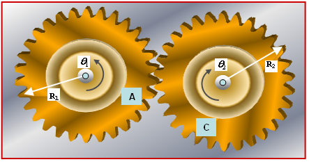
The image below shows a right angle bevel gear pair. Bevel gear 1, with a pitch radius R1, is connected to Ground with Revolute Joint 1. It is allowed to rotate about a fixed axis. Bevel gear C, with a pitch radius R2 is connected to Ground with Revolute Joint 2, and is allowed to rotate about a fixed axis.
We are interested in defining the overall effect of the bevel gear set, for example, the coupling of the rotations in the two revolute joints. We are not interested in the tooth forces that occur at the contact between the two gears. We also assume that the gear mating is perfect and that there is no backlash, no tooth deflection, no eccentricity, or other manufacturing defects.
Assume that the rotation of Gear A is θ1 and that the rotation of Gear C is θ2. Then the two rotations can be related by the algebraic relationship:
<Constraint_Coupler
     id              = "1"
     joint1_id       = "1"
     freedom_1       = "R"
     joint2_id       = "2"
     freedom_1       = "R"
     coefficients    = "10.0,15.0"
</Constraint_Coupler>
Assume that the radius of the pinion gear is 30mm and the system length units are in millimeters. The Constraint_Coupler that defines this scenario may be written as:
<Constraint_Coupler
     id              = "2"
     joint1_id       = "51"
     freedom_1       = "T"
     joint2_id       = "41"
     freedom_2       = "R"
     coefficients    = "1.0,30.0"
</Constraint_Coupler >
The image below demonstrates a third example of a Constraint_Coupler. In this case, the translations in two joints are coupled. The image is a schematic of a hydraulic jack often used in auto repair shops. The hydraulic press consists of two cylinders of very different diameters D1 and D2 connected to each other. Two pistons enclose the volume and an incompressible fluid fills the enclosed volume of the press.
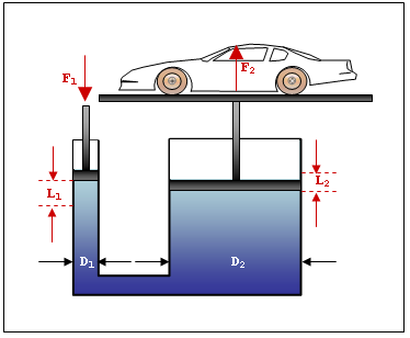
The area of the cylinder on the left A1 = πD12/4.
The area of the cylinder on the right A2 = πD22/4.
Assume a force F1 is applied on the left cylinder, causing it to move by a distance L1. We are interested in calculating the displacement of the car L2 and the lifting force F2.
Since the fluid is incompressible, movement of the left piston causes a volume = L1*A1 to be displaced. This must cause the piston on the right to move up so that fluid volume is preserved. The volume of the right cylinder increases by L2*A2.
The incompressibility condition leads to: L1*A1 + L2*A2 = 0
MotionSolve uses the principle of virtual work to automatically calculate the relationship between F1 and F2, given the kinematic relationship in xml-format_36.htm#xml-format_36__equation-figure_hhs_5tq_vcb.
- D1 = 5.08mm, for example A1 = 20.1885 mm2
- D2 = 50.8mm, for example A2 = 2018.85 mm2
- The piston on the left is on Translational Joint 123
- The piston on the right is on Translational Joint 456
The Constraint_Coupler statement that describes Equation 3 is:
<Constraint_Coupler
     id              = "5"
     joint1_id       = "123"
     freedom_1       = "T"
     joint2_id       = "456"
     freedom_2       = "T"
     coefficients    = "20.1885,2018.85"
</Constraint_Coupler
>
Comments
- Constraint_Coupler
defines an algebraic constraint. The constraint can be linear or nonlinear.
The linear form of the constraint is: In Equation 2 above, M1, M2 and M3 are coordinate measures of the selected degree of freedom in the selected joints. If Ik and Jk are the I and J markers of Constraint_Joint k, then Mk means the following:
- Revolute joint: AZ(Ik,Jk)
- Translational joint: DZ(Ik,Jk,Jk)
- Cylindrical joint: DZ(Ik,Jk,Jk) if FREEDOM_K = "T" AZ(Ik,Jk) if FREEDOM_K = "R"
When Equation 2 contains only two joints, s1 and s2 need to be specified. These are the first and second values specified for ratio.
When equation (6) contains three joints, s1, s2 and s3 need to be specified. S1 is the first value specified for ratio. S2 is the second value specified for ratio. S3 is the third value specified for ratio.
- Constraint_Coupler may
also be used to specify nonlinear relationships. In this case, the
kinematic relationship may be expressed as:
The user defined subroutine COUSUB is used to specify Equation 3 equation . In addition to the above, MotionSolve also requires you to provide the first partial of Equation 3 with respect to M1, M2, and M3. This data is provided to MotionSolve in the user defined subroutine COUXX. Similarly, the second partials are to be returned in a third user defined subroutine COUXX2. M1, M2, and M3 are passed in as arguments to the user defined subroutines.
- When a nonlinear Constraint_Coupler is defined, Equation 3 (defined in the user defined subroutine COUSUB) is required to be twice differentiable.