
Force: Two Body Vector
Model ElementForce_Vector_TwoBody defines a general force and/or torque acting between two Reference_Markers.
Description
It can be used to model a force, a torque, or both. The force and/or torque vectors are defined by their three components with respect to a third Reference_Marker. The components may be defined using MotionSolve expressions or a user-defined subroutine. They may be a function of any system state and time.
Format
- A pure force: ForceOnly.
- A pure torque: TorqueOnly.
- A force and a torque: ForceAndTorque.
For the sake of clarity, the formats for the three variations are shown separately.
<Force_Vector_TwoBody
   id                     = "integer"
   i_marker_id            = "integer"
   j_floating_marker_id   = "integer"
 [
   ref_marker_id          = "integer"
   label                  = "integer"
 ]
   type                   = "ForceOnly"
 [
   fx_expression          = "expression"
   fy_expression          = "expression"
   fz_expression          = "expression"

   usrsub_dll_name        = "valid_path_name"
   usrsub_param_string    = "USER(par_1, ... par_n)"
   usrsub_fnc_name        = "custom_fnc_name"

   script_name            = "valid_path_name"
   interpreter            = "string"
   usrsub_param_string    = "USER(par_1, ..., par_n)"
   usrsub_fnc_name        = "custom_fnc_name"
  ]
/><Force_Vector_TwoBody
id = "integer"
i_marker_id = "integer"
j_floating_marker_id = "integer"
[
ref_marker_id = "integer"
label = "integer"
]
type = "TorqueOnly"
[
tx_expression = "expression"
ty_expression = "expression"
tz_expression = "expression"
usrsub_dll_name = "valid_path_name"
usrsub_param_string = "USER(par_1, ... par_n)"
usrsub_fnc_name = "custom_fnc_name"
script_name = "valid_path_name"
interpreter = "string"
usrsub_param_string = "USER(par_1, ..., par_n)"
usrsub_fnc_name = "custom_fnc_name"
]
/><Force_Vector_TwoBody
id = "integer"
i_marker_id = "integer"
j_floating_marker_id = "integer"
[
ref_marker_id = "integer"
label = "integer"
]
type = "ForceAndTorque"
[
fx_expression = "expression"
fy_expression = "expression"
fz_expression = "expression"
tx_expression = "expression"
ty_expression = "expression"
tz_expression = "expression"
usrsub_dll_name = "valid_path_name"
usrsub_param_string = "USER(par_1, ... par_n)"
usrsub_fnc_name = "custom_fnc_name"
script_name = "valid_path_name"
interpreter = "string"
usrsub_param_string = "USER(par_1, ..., par_n)"
usrsub_fnc_name = "custom_fnc_name"
]
/>Attributes
- id
- Element identification number (integer > 0). This number is unique among all Force_Vector_TwoBody elements.
- label
- The name of the Force_Vector_TwoBody element.
- i_marker_id
- Specifies the Reference_Marker at which the force is applied. This is designated as the point of application of the force.
- j_floating_marker_id
- Specifies the Reference_Marker at which an equal and opposite reaction force is applied. This marker is moved around on the parent body so that it is always superimposed on i_marker_id. Such a construct allows Newton's third law to be automatically fulfilled.
- ref_marker_id
- Specifies the Reference_Marker whose coordinate system is used as the basis for defining the components of the force vector.
- type
- Select from "ForceOnly", "TorqueOnly", and
"ForceAndTorque".
- "ForceOnly"
- Implies that the element applies a force between the two Reference_Markers. No torque is applied.
- "TorqueOnly"
- Implies that the element applies a torque between the two Reference_Markers. No force is applied.
- "ForceAndTorque"
- Implies that the element applies a force and a torque between the two Reference_Markers.
- fx_expression, fy_expression, fz_expression
- Specifies the three components of the force vector as function expressions.
- tx_expression, ty_expression, tz_expression
- Specifies the three components of the torque vector as function expressions.
- usrsub_param_string
-
The list of parameters that are passed from the data file to the user-defined subroutine. Use this keyword only when type = USERSUB is selected. This attribute is common to all types of user subroutines and scripts. The name of the user-subroutine depends on the type of the element.
- "ForceOnly" uses a VFOSUB
- "TorqueOnly" uses a VTOSUB
- "ForceAndTorque" uses a GFOSUB
- usrsub_dll_name
- Specifies the path and name of the DLL or shared library containing user subroutine. MotionSolve uses this information to load the user subroutine in the DLL at run time.
- usrsub_fnc_name
- Specifies an alternative name for the user subroutines VFOSUB, VTOSUB, or GFOSUB.
- script_name
- Specifies the path and name of the user written script that contains the routine specified by usrsub_fnc_name.
- interpreter
- Specifies the interpreted language that the user script is written in (example: "PYTHON"). See User-Written Subroutines for a choice of valid interpreted languages.
Example
The first example shows how the damping in a nonlinear bushing may be modeled using this component.
Bushings are used as compliant connectors in numerous applications. They are often made of material like rubber or polyurethane, and exhibit nonlinear stiffness and damping properties. Bushings are often tested in the lab and the test data is provided as input to MotionSolve. "Synthesized" test data for a bushing is shown in the image below.

For this example, assume a bushing was tested and three curves, 1-3, are available. These specify the dependency of the bushing damping force on deflection velocity for each of the three translational directions. The bushing connects two Reference_Markers: "1801" on Body 18 and "1901" on Body 19. We want to model the nonlinear bushing damping force in MotionSolve. Reference_Markers "1903" is the connection point of the bushing on Body 19.
The Force_Vector_TwoBody modeling element for this scenario is:
<Force_Vector_TwoBody
     id                     = "18"
     label                  = "My-Automotive-Bushing"
     type                   = ForceOnly
     i_marker_id            = "1801"
     j_floating_marker_id   = "1901"
     ref_marker_id          = "1903"
     fx_expression          = "CUBSPL(0, VX(1801,1903,1903,1903), 1)"
     fy_expression          = "CUBSPL(0, VY(1801,1903,1903,1903), 2)"
     fz_expression          = "CUBSPL(0, VZ(1801,1903,1903,1903), 3)"
/>
The following points are worth noting:
In the example, we have chosen to use Reference_Marker "1903" as the reference coordinate system for the bushing. The time derivative of the displacement vector is therefore taken in the reference frame of Reference_Marker "1903". This is not the same as taking the time derivative in the Global Reference Frame. The reference frame for time derivatives is the last parameter in the argument list for VX(), VY(), and VZ() functions.
- This is a very simple damping model. Most bushings exhibit non-linearities like hysteresis and frequency/amplitude dependent behavior. These are ignored in this example.
- A stiffness model could also be added to the force expressions for this model, thereby creating one component that models both the stiffness and damping properties.
- Three curves, with IDs 4-6, specifying bushing force versus bushing deflection.
- Three curves, with IDs 7-9, specifying bushing torque versus bushing angular deflection rate.
- Three curves, with IDs 10-12, specifying bushing torque versus bushing angular deflection.
These could be used to augment the earlier model to create a more comprehensive user-defined bushing that models deflection and velocity dependent forces and torques. The augmented model would look like this:
<Force_Vector_TwoBody
     id                     = "18"
     label                  = "My-Automotive-Bushing"
     type                   = ForceAndTorque
     i_marker_id            = "1801"
     j_floating_marker_id   = "1901"
     ref_marker_id          = "1903"
     fx_expression          = "CUBSPL(0, VX(1801,1903,1903,1903),1)  + CUBSPL(0, DX(1801,1903,1903),4)"
     fy_expression          = "CUBSPL(0, VY(1801,1903,1903,1903),2)  + CUBSPL(0, DY(1801,1903,1903),5)"
     fz_expression          = "CUBSPL(0, VZ(1801,1903,1903,1903),3)  + CUBSPL(0, DZ(1801,1903,1903),6)"
     tx_expression          = "CUBSPL(0, WX(1801,1903,1903), 7)      + CUBSPL(0, AX(1801,1903), 10)"
     ty_expression          = "CUBSPL(0, WY(1801,1903,1903), 8)      + CUBSPL(0, AY(1801,1903), 11)"
     tz_expression          = "CUBSPL(0, WZ(1801,1903,1903), 9)      + CUBSPL(0, AZ(1801,1903), 12)"
/>WX(), WY(), and WZ() measure the angular deflection rate in the bushing while AX(), AY() and AZ() measure angular deflection in the bushing. The angular deflections are assumed to be small (less than 10 degrees).
Comments
- i_marker_id is designated as the point of application of the Force_Vector_TwoBody. j_floating_marker_id is the point of reaction.
- The image below shows an exploded view of a
Force_Vector_TwoBody acting between two bodies. It also shows
the key force calculations.
Figure 2. An Exploded View of a Force_Vector_Two_Body 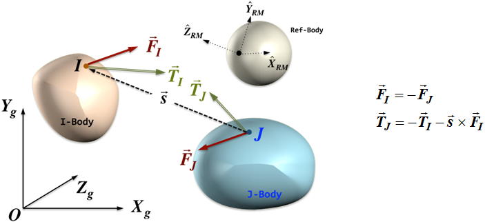
- Since j_float_id is always placed on top of i_marker_id, Newton's third law is correctly applied. A pure force applied at i_marker_id results in an equal and opposite force acting at j_floating_marker_id. As j_floating_marker_id moves with respect to its parent body, appropriately varying moment is applied to its parent body.
- If you want to model the force only at the point of action and not the reaction, simply define j_floating_marker_id to be on ground. MotionSolve does not calculate any reaction forces or torques. It should, however, tell you how the reaction point is moving relative to the ground coordinate system.
- The force and torque expressions (or user subroutines) must be smooth and preferably differentiable. This enables the numerical methods to deal with the force effectively.
- If you are using velocity measures like VX(), VY(), and VZ() to calculate a damping force, make sure that the time derivative is taken in the correct reference frame. See the example for more information.
- Force_Vector_TwoBody can act on all types of bodies: Body_Rigid, Body_Flexible, and Body_Point.
- Any force defined in MotionSolve
must meet the following criteria:
- The force is a continuous function with respect to its input arguments. Simply stated, this means that if you were to draw the force as a function of any one of its arguments on paper, you would not need to ever lift the pen off the paper.
- The derivative of the force with respect to its input variables is always finite. Once again, simply stated, this means that if you were to plot the force versus input variable on paper, the curve would have no vertical segments. A vertical segment represents an infinite slope that the computer would have difficulty dealing with.
- The following are desirable characteristics for forces
defined in MotionSolve:
- Force should be differentiable with respect to all of its input variables. In simple terms, this means that the force should ideally not have any sharp corners or kinks in its definition. Instead, it should be smooth. A smooth force is more easily handled by the numerical methods than a force with kinks or corners.
- When writing user-subroutines for forces, do not use common-blocks (in Fortran) or global variables (C) to pass state dependent information between different user-written subroutines. Instead, use the access functions SYSFNC() or SYSARY() to obtain the data in the user-written subroutine and recalculate it. Sometimes, it is useful to use a Reference_Variable for storing the intermediate results. This allows an intermediate result to be accessed via SYSFNC() without the need for recalculating the result.