
Body: Rigid
Model ElementBody_Rigid defines a rigid body object in MotionSolve. This entity has mass and inertia properties.
Format
< Body_Rigid
     id            = "integer"
 [   label         = "string"             ]
     cg_id         = "integer"
 [   im_id         = "integer"            ]
     lprf_id       = "integer"
 [   isground      = { "TRUE"|"FALSE" }   ]

     mass          = "real"
 [
     inertia_xx    = "real"
     inertia_yy    = "real"
     inertia_zz    = "real"
     inertia_xy    = "real"
     inertia_yz    = "real"
     inertia_xz    = "real"
 ]
 [   v_ic_x        = "real"
     v_ic_y        = "real"
     v_ic_z        = "real"
     w_ic_x        = "real"
     w_ic_y        = "real"
     w_ic_z        = "real"
     v_ic_x_flag   = {"TRUE"|"FALSE"}
     v_ic_y_flag   = {"TRUE"|"FALSE"}
     v_ic_z_flag   = {"TRUE"|"FALSE"}
     w_ic_x_flag   = {"TRUE"|"FALSE"}
     w_ic_y_flag   = {"TRUE"|"FALSE"}
     w_ic_z_flag   = {"TRUE"|"FALSE"}
     vm_id         = "integer"
     wm_id         = "integer"
 ]
 [
     is_wet_body   = {"TRUE"|"FALSE"}
     cp_inp_id     = "integer" ]
/>
Attributes
- id
- Element identification number, (integer>0). This is a number that is unique among all Body_Rigid elements.
- label
- The name of the Body_Rigid element.
- cg_id
- Specifies the ID of the Reference_Marker that is located at the center-of-mass of the Body_Rigid, called the CG marker.
- im_id
- Defines a Reference_Marker that specifies the origin and the coordinate system in which the inertia matrix is specified. This marker is called the IM marker. im_id is optional. When not specified, it defaults to cg_id.
- lprf_id
- Optional attribute to specify the local part reference marker. This marker is used as the coordinate system for all locations and orientations.
- isground
- Specifies whether the rigid body being defined is the ground body or not.
The value "TRUE" indicates that the rigid body that is being defined is the ground body. The value "FALSE" indicates that the rigid body is not the ground body.
The attribute isground is optional. When not specified, it defaults to "FALSE".
- mass
- Specifies the mass of the Body_Rigid object. When specified, mass must be a positive number. The attribute mass is optional. If a rigid body is fully constrained and you are not interested in the constraint forces, then mass need not be specified. When omitted, zero mass is assumed.
- inertia_xx, inertia_yy, inertia_zz, inertia_xy, inertia_yz, inertia_xz
- Define the moments of inertia and the products of inertia of the rigid body about the origin
im_id and about its x-, y- and z-axes, respectively.
See Comments 4-9 for more information about these quantities.
The attributes inertia_xx, inertia_yy, inertia_zz, inertia_xy, inertia_yz and inertia_xz are optional. If a rigid body is fully constrained and one is not interested in the constraint forces, then these need not be specified. When specified:
inertia_xx > 0
inertia_yy > 0
inertia_zz > 0
- v_ic_x
- Specifies the initial translational velocities of the Body_Rigid CG marker along the global x-axis.
- v_ic_y
- Specifies the initial translational velocities of the Body_Rigid CG marker along the global y-axis.
- v_ic_z
- Specifies the initial translational velocities of the Body_Rigid CG marker along the global z-axis.
- w_ic_x
- Specifies the initial rotational velocity about the X-axes of the Body_Rigid CG marker.
- w_ic_y
- Specifies the initial rotational velocity about the Y-axes of the Body_Rigid CG marker.
- w_ic_z
- Specifies the initial rotational velocity about the Z-axes of the Body_Rigid CG marker.
- v_ic_x_flag
- A Boolean flag that indicates whether the x-velocity is known exactly or is just an initial
guess.
"TRUE" means this initial condition is applied exactly unless it is in conflict with a Motion input.
"FALSE" means this initial condition is applied as an initial guess. It may be changed by MotionSolve to ensure that all constraints are satisfied.
- v_ic_y_flag
- A Boolean flag that indicates whether the y-velocity is known exactly or is just an initial
guess.
"TRUE" means this initial condition is applied exactly unless it is in conflict with a Motion input.
"FALSE" means this initial condition is applied as an initial guess. It may be changed by MotionSolve to ensure that all constraints are satisfied.
- v_ic_z_flag
-
A Boolean flag that indicates whether the z-velocity is known exactly or is just an initial guess.
"TRUE" means this initial condition is applied exactly unless it is in conflict with a Motion input.
"FALSE" means this initial condition is applied as an initial guess. It may be changed by MotionSolve to ensure that all constraints are satisfied.
- w_ic_x_flag
- A Boolean flag that indicates whether the angular velocities along the x-axis are known exactly or is just an initial guess.
- w_ic_y_flag
- A Boolean flag that indicates whether the angular velocities along the y-axis are known exactly or is just an initial guess
- w_ic_z_flag
- A Boolean flag that indicates whether the angular velocities along the z-axis are known exactly or is just an initial guess
- vm_id
- Reference marker for translation initial velocities.
- wm_id
- Reference marker for angular initial velocities.
- is_wet_body
- A Boolean flag that determines whether this body will receive fluid loads from the corresponding
fluid model while in co-simulation with AcuSolve.
"TRUE" means that forces and torques computed in the AcuSolve simulation will be applied to the center of gravity of this body.
"FALSE" means that forces and torques computed in the AcuSolve simulation will not be applied to this body. 18
- cp_inp_id
- Specifies the ID of the Control_PlantInput element that holds the forces and torques computed in the AcuSolve simulation that will be applied to this rigid body. This attribute is only used when performing a co-simulation between MotionSolve and AcuSolve. 18
Example
<Body_Rigid
     id                  = "1"
     cg_id               = "0"
     isground            = "TRUE"
/><Body_Rigid
id = "2"
cg_id = "21"
isground = "FALSE"
/><Body_Rigid
id = "2"
cg_id = "21"
im_id = "21"
isground = "FALSE"
mass = "1.0"
v_ic_x = "0."
v_ic_y = "0."
v_ic_z = "0."
v_ic_x_flag = "FALSE"
v_ic_y_flag = "FALSE"
v_ic_z_flag = "FALSE"
/><Body_Rigid
id = "2"
lprf_id = "1"
cg_id = "21"
im_id = "21"
isground = "FALSE"
mass = "1.0"
inertia_xx = "0.0004892316"
inertia_yy = "0.0004892316"
inertia_zz = "0.0004892316"
inertia_xy = "0."
inertia_yz = "0."
inertia_yz = "0."
v_ic_x = "1.0"
v_ic_y = "0."
v_ic_z = "0."
w_ic_x = "2.0"
w_ic_y = "0."
w_ic_z = "0."
v_ic_x_flag = "FALSE"
v_ic_y_flag = "FALSE"
v_ic_z_flag = "FALSE"
w_ic_flag = "FALSE"
/> Comments
- The Body_Rigid operates in 3D space by default, though it can later be redefined to be planar in a Reference_2DCluster object.
- The global coordinate system is anchored on a special, immovable Body_Rigid that has the attribute isground = "TRUE". This body is called the "Ground body". It is fixed in absolute space and defines the global origin and orientation.
- A Body_Rigid may have Post_Graphic objects attached to it. Graphic objects help visualize the shape and size of a rigid body. They may also be used for defining general 3D contact between rigid bodies.
- A Body_Rigid may be given zero values for mass and inertia, if it is fully constrained. For example, if all its six degrees of freedom are defined in some way by algebraic relationships. Such bodies are known as "dummy bodies". Their sole purpose is to connect other modeling entities together.
- If a body is given a non-zero mass, then it must be provided with a CG marker.
- MotionSolve does not use Euler Angles to represent large rotations. Consequently, it does not suffer from "Euler Singularity" problem, where the angles defining the 3-D rotation are non-unique.
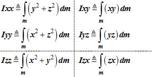
- The terms
Ixx,Iyy, Izz ,
Ixy, Iyz, Izx are
defined as follows:
- The inertia matrix is defined in terms of
Ixx,Iyy, Izz ,
Ixy, Iyz, Izx
as:
- The inertia matrix must be positive definite.
As a consequence of positive definiteness, the inertia matrix must satisfy the
following properties:
- The eigenvalues of I are all real and positive. These are the principal moments of inertia of the body.
- The eigenvectors of I are real and orthogonal. These are the principal axes of the body.
- If the 3x3 matrix F
represents the eigenvectors of a body, then:Ix, Iy, Izare the principal moments of inertia
- The principal moments of inertia must satisfy
the "triangle inequality":
- The principal moments of inertia and the
mass, m, are related through the
relationships:
Rx, Ry, Rz are the radius of gyration in the x, y and z-direction, respectively
The radii of gyration contain information about the mass distribution in the rigid body. They are related to the physical dimensions of the rigid body.
- When defining dummy bodies, use physically
meaningful mass and inertia properties. If you want to define a dummy body made
of steel, physically realistic dummy body properties are:
- Kg-m units: mass = 1; Ix=1E-3, Iy=1E-3, Iz=1E-3
- Kg-mm units: mass = 1; Ix=1E+3, Iy=1E+3, Iz=1E+3
- lb-in units: mass = 1; Ix=1.55, Iy=1.55, Iz=1.55
- It is not possible to selectively apply initial angular velocities. Either all are applied or none are applied.
- When isground is "TRUE", all mass/inertia and initial velocity attributes, if specified, are ignored.
- The total number of initial conditions
specified for the entire system should not exceed the number of degrees of
freedom. If the number of initial conditions exceeds the degrees of freedom,
MotionSolve may change some or all of the
initial conditions to be consistent with the constraints.
Note, initial velocities may also be specified using Jointlnitialvel_Trans, Jointlnitialvel_Trans and Jointlnitialvel_Cyl cards.
Consider the simple pendulum shown below.Figure 1. 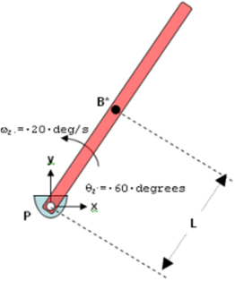
Assume that the pendulum body (shown in red) is pivoted at the global origin by a revolute joint, such that rotation is allowed about the global z-axis. The center-of-mass of the pendulum, B*, is at a distance L from the pivot P.
The pendulum is initially defined such that its axis makes an angle of 60 degrees with the global x-axis and it rotates counterclockwise about the global z-axis at 20 degrees/second.
For this configuration, the initial translational velocities of B* in the global coordinate system may be calculated as:
Vx = -L * ωz * Sin(60d) = -0.8667 * L * ωzVy = L * ωz * Cos(60d) = 0.5000 * L * ωzThis system has one degree of freedom. Thus only one initial velocity may be specified. You have the option of specifying Vx, Vy or ωz. The revolute joint, which imposes the constraint Distance (PB*) = L, imposes the other velocities automatically using equations Equation 7 and Equation 8.
Now consider the situation where you specify initial values for Vx, Vy and ωz. If the conditions (1) and (2) are not satisfied by the initial values you specify, MotionSolve changes Vx, Vy and/or ωz so that Equation 7 and Equation 8 are satisfied.
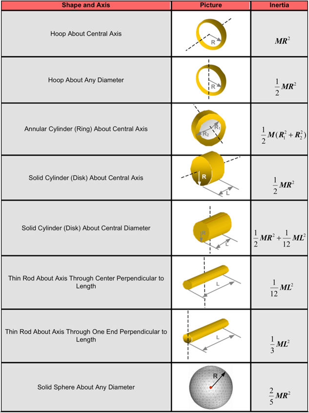
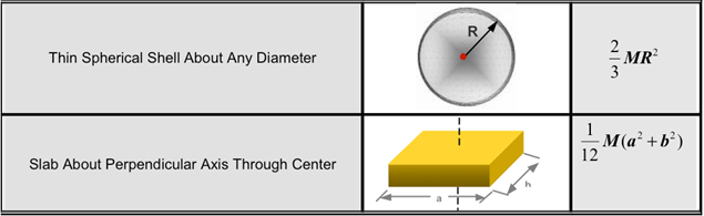
- The table below shows the moments of inertias
of commonly occurring solid shapes.
- Co-simulation with AcuSolve requires you to identify which rigid bodies will
interact with the fluid domain. To do this, the "wet" body must be identified by
setting the is_wet_body attribute to "TRUE".
Additionally, the cp_inp_id must be specified as a valid
Control_PlantInput ID which holds the values of three
forces and three torques for the X, Y and Z directions. These forces and torques
are then applied to the rigid body as a fluid load.Note: If is_wet_body is specified as "TRUE" and the simulation is not coupled with AcuSolve, then MotionSolve ignores the is_wet_body and cp_inp_id attributes and their values.