HM-4640: Dummy Positioner
Tutorial Level: Advanced In this tutorial, you will learn the different Default functionalities available to position a dummy in its environment.
The driver seat and environment used in this tutorial are based on the LS-DYNA Toyota Yaris model, provided on the National Crash Analysis Center (NCAC) website.
The LS-DYNA dummy model used in this tutorial is a release version of the THOR-Mod Kit/Metric crash test dummy with SD3 shoulder posted on the NHTSA website.
Load the LS-DYNA Profile
In this step, you will load the LS-DYNA profile in HyperMesh.
- Start HyperMesh.
- Set the Profile to LsDyna.
Retrieve and View the Model File
In this step, you will open the model file and view it in HyperMesh.
- From the menu bar, click .
- In the dialog, open the dummy_positioner.hm file.
Position the Dummy to its H-Point Location
In this step, you will move the dummy to its H-Point Location on the seat.
-
From the Safety ribbon, click the
Dummy tool.
Figure 2. 
-
In the Dummy Browser, click the
THOR_FE dummy entity to activate the global
positioning parameters in the Entity Editor.
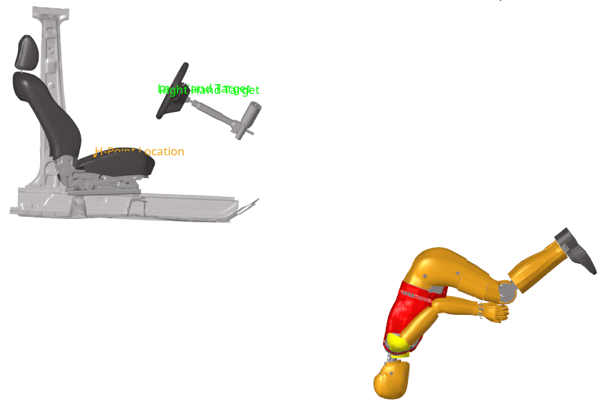
Figure 3. 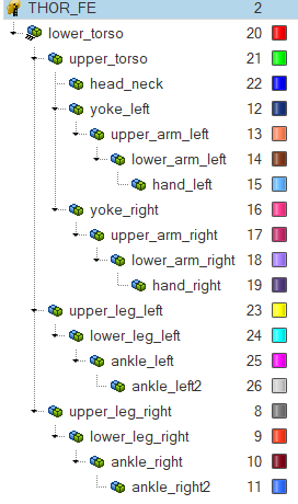
-
In the Entity Editor, for the Global rotation attribute
Rx, enter 180.
The dummy rotates.
-
In the modeling window, select
the node tagged as H-Point Location as seen in Figure 4.
Figure 4. 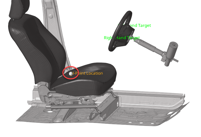
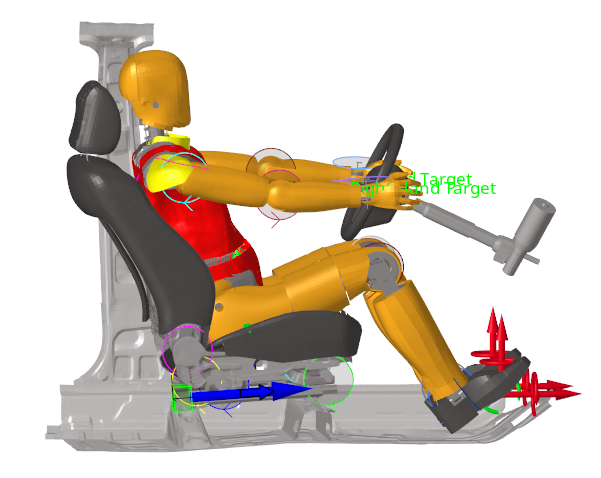
The dummy automatically moves to the selected H-Point location.Figure 5. 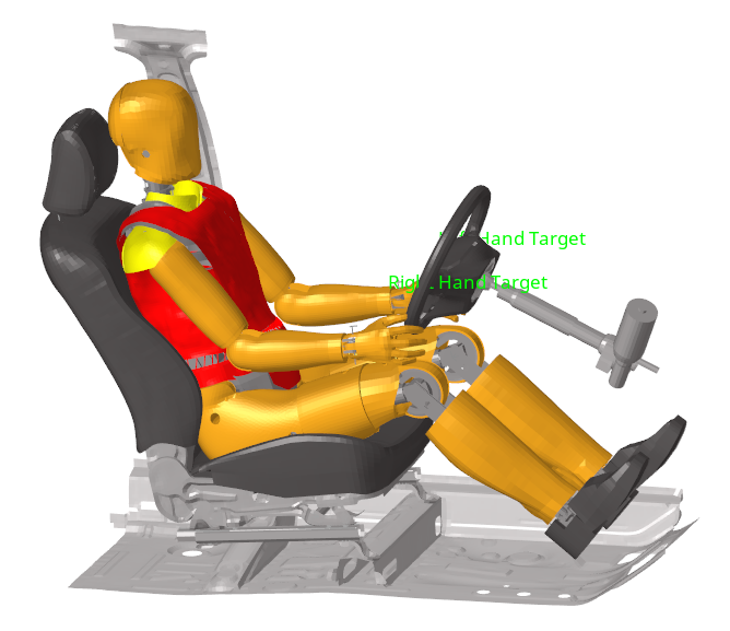
Manually Position the Limbs
In this step, you will manually position the lower_leg_left and lower_leg_right body entities.
-
In the Dummy Browser, click the
lower_leg_left body entity.
Figure 6. 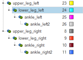
The joint manipulator appears in the modeling window, and the Entity Editor opens.Figure 7. 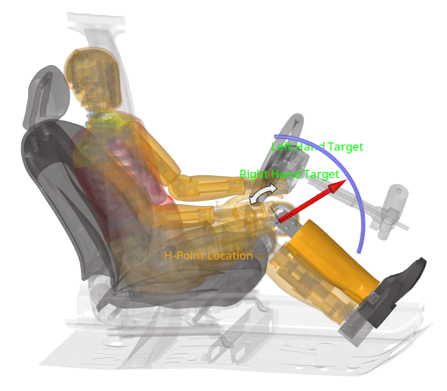
-
Position the lower leg by completing one of the following:
- In the modeling window, select the smallest blue arc on the manipulator to interactively position the lower leg to an angle value of -70°.
- In the Entity Editor, Current angle field, enter -70.
- In the Dummy Browser, click the lower_leg_right body entity.
- Repeat step 2.
Automatically Position the Hands
In this step, you will position the hands automatically.
- In the Dummy Browser, right-click the THOR_FE dummy entity and select Move Limbs from the context menu.
- Set Multiple pairs to Yes.
- Click the Select pairs field.
-
Position the left hand.
-
In the modeling window, select the node tagged
as Left Hand Target as seen in Figure 8.
Figure 8. 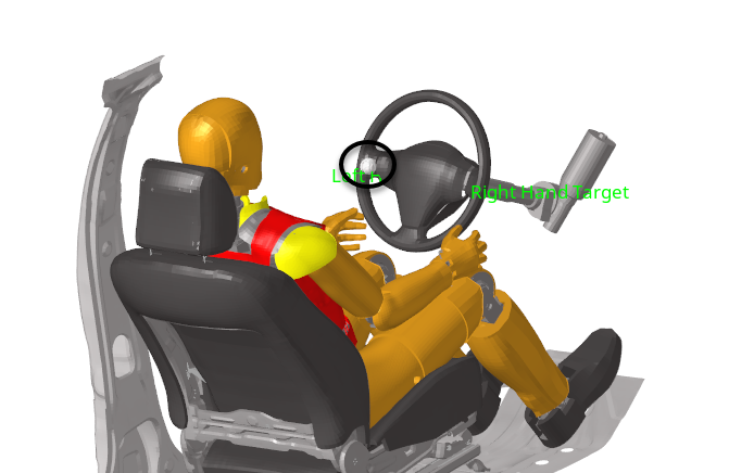
-
In the modeling window, select the node tagged
as Left Hand Target as seen in Figure 8.
-
Position the right hand.
-
In the Select multi nodes dialog, click
 to
add a second row to define the Source Point and Target Point for the
right hand.
to
add a second row to define the Source Point and Target Point for the
right hand.
-
In the modeling window, select the node tagged
as Right Hand Target as seen in Figure 9.
Figure 9. 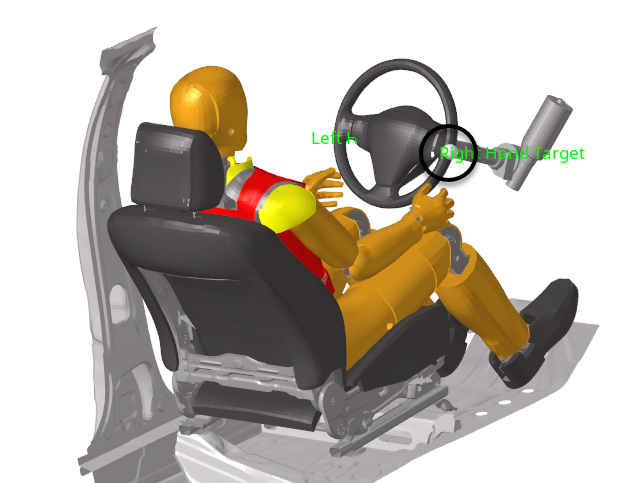
-
In the Select multi nodes dialog, click
- In the Select multi nodes dialog, click Close.
-
Click Select Bodies.
Figure 10. 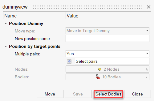
-
In the Dummy Bodies DOF dialog, enable/disable dummy
bodies and body DOFs to be taken into account for the automatic positioning of
the dummy limbs.
-
In the dummyview dialog, click Move
to activate automatic limbs positioning.
Figure 11. 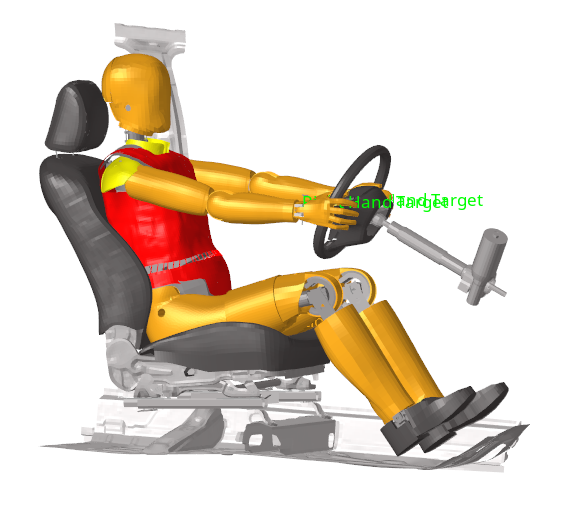
Save and Retrieve Dummy Positions
In this step, you will save and retrieve dummy positions.
- In the Dummy Browser, right-click the THOR_FE dummy entity and select from the context menu.
-
In the Update Position info dialog, enter Final
Position in the Name field and click
Close.
The actual position of the dummy is saved and can be retrieved for future reference.
-
To retrieve the initial dummy position, in the Dummy Browser, right-click the THOR_FE dummy entity and select from the context menu.
The dummy automatically moves to its initial position.
-
To retrieve the saved dummy position, in the Dummy Browser,
right-click the THOR_FE dummy entity and select .
- In the Positions dialog, select Final Position and click Close.
Link the Dummy to a Seat Mechanism
In this step, you will link the dummy to a seat mechanism.
-
From the Safety ribbon, click the
Mechanism tool.
Figure 12. 
The Mechanism Browser opens. -
In the Mechanism Browser, expand the
Driver_Seat mechanism to observe the different joints
and bodies defined.
Figure 13. 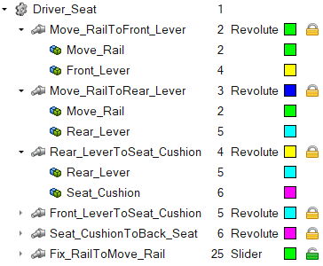
- Right-click the Driver_Seat mechanism entity and select Link To Dummy from the context menu.
- In the Dummies dialog select THOR_FE and click Next.
-
In the Mechanism Bodies [Parent Body] dialog, select
Seat_Cushion and click
Next.
This body will be the parent body that will drive the motion of the dummy. In the Mechanism Bodies [Parent Body] dialog, the body containing the H-Point of the dummy is automatically selected, and the Body's DOF linked with the master body are automatically setup as TX; TY; TZ, which is sufficient.
-
Click Close to finalize the linking of the dummy to the
seat mechanism.
At this point, any motion of the seat will result in an according global motion of the dummy. It is also possible to constrain some bodies of the dummy that may remain in position, such as the feet.
-
Create a constraint on the ankle_left2 body.
- Create a constraint on the ankle_right2 body and node id=581450 with the same fixed DOF.
- In the Mechanism Browser, right-click the Fix_RailToMove_Rail joint and select Move from the context menu.
-
In the Entity Editor, Current Distance field, enter
-50.0.
Notice how the dummy moves with the seat and how the position of the legs and feet are updated because of the constraints defined on the feet.
Figure 14.