Create Subsystems and Attachments
Tutorial Level: Intermediate In this tutorial, you will learn how to create and connect subsystems and attachments.
Before you begin, copy the file(s) used in this tutorial to your
working directory.
In this tutorial you will:
- Open the Include, Part, and Subsystem Browsers
- Create new subsystems
- Create attachments in the door
- Create attachments in the body
- Connect the attachments
- Save representation
- Unload and load a representation
Open Include, Part, and Subsystem Browsers
- Start HyperMesh.
- From the menu bar, click .
-
Browse to your working directory, select
Yaris_BIW_and_Door.hm, and click
Open.
The model opens in the modeling window.
Figure 1. 
- From the Model Browser, double-click Include Files to open the Include Browser.
-
From the Assembly ribbon, select the
Parts tool to open the Part Browser.
Figure 2. 
-
From the Assembly ribbon, select the
Subsystems tool to open the Subsystem Browser.
Figure 3. 
-
Left-click and drag the Subsystem Browser to the right side
of the screen as shown in Figure 4.
Figure 4. 
Create New Subsystems
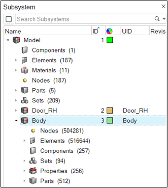
- From the Part Browser, click the Front_Door_RH part assembly under and drag it into the Subsystem Browser.
- From the Subsystem Browser, select the newly created subsystem named Subsystem1.
- From the Entity Editor, rename the new subsystem from Subsystem1 to Door_RH.
-
Set the UID to Door_RH.
Figure 5. 
- From the Include Browser, right-click Subsystem1, select Rename from the context menu, and enter Door_RH.fm as the name.
-
From the Include Browser, click
Body.fem and drag it into the Subsystem Browser.
A new subsystem named Body has been created.
Figure 6. 
Create Attachments in the Door
-
From the Subsystem Browser, right-click on the
Body subsystem and select Hide
from the context menu.
In the modeling window, only the Door_RH subsystem is displayed.
Figure 7. 
-
From the Connectors ribbon, select the
Attachment tool.
Figure 8. 
-
From the guide bar, click
Undefined and select Create
New/Edit from the drop-down menu.
The Connector Control Manager dialog opens.
- In the Attachments tab of the Connector Control Manager dialog, click on spider.
- Verify that Controller is set to RigidSpider.
-
Change Connect outer layer to every node.
Figure 9. 
-
Close the dialog.
In the Attachments guide bar, the control is set to spider.
-
From the guide bar, click
 .
.
- Set Selection to Automatic.
-
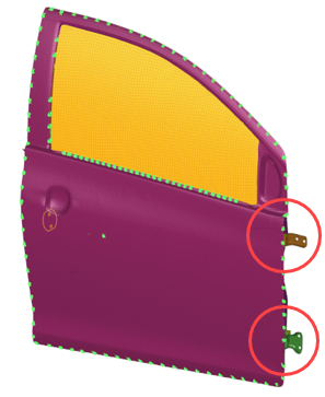
Zoom in on the locations shown in Figure 10 and Figure 11 and select the parts with holes.
Figure 10. 
Figure 11. 
-
From the guide bar, verify that the
Realize check box is selected and click
 to create and realize the attachments.
Create Attachments in the Body
- From the Subsystem Browser, right-click on the Body subsystem and select Isolate from the context menu.
-
From the Connectors ribbon, select the
Attachment tool.
Figure 12. 
-
From the guide bar, click
 .
.
- Set Selection to Manual.
- From the guide bar, click Undefined and select spider from the drop-down menu.
-
Zoom in on the locations shown in Figure 13 and select one node around each hole as shown in Figure 14 and Figure 15.
Figure 13. 
Figure 14. 
Figure 15. 
-
From the guide bar, verify that the
Realize check box is selected and click
 to create and realize the attachments.
- From the guide bar, click spider and select Create New/Edit from the drop-down menu to open the Connector Control Manager dialog.
-
From the Attachments tab, click on node and verify
Controller is set to Node.
Figure 16. 
-
Close the Connector Control Manager dialog.
In the Attachments guide bar, the control is set to node.
-
Zoom in on the locations shown in Figure 17 and select the nodes shown in Figure 18.
Figure 17. 
Figure 18. 
-
From the guide bar, click
 to
create and realize the attachments.
- From the Subsystem Browser, right-click on the Door_RH subsystem and select Show from the context menu.
Connect the Attachments
-
From the Connectors ribbon, select the
Connect tool.
Figure 19. 
- From the guide bar, click Undefined and select Create New/Edit from the drop-down menu to open the Connector Control Manager dialog.
- From the Connect Attachments tab, right-click and select Create from the context menu.
- Rename the connector control to CBAR_Control.
-
Set Type to bolt(CBAR).
Figure 20. 
-
Close the dialog.
In the guide bar, the control is set to CBAR_Control.
-
From the guide bar, click
 to open the Select Attachments dialog.
-
From the Select Attachments dialog, select all twelve
attachments and click OK.
Figure 21. 
-
From the guide bar, verify that the
Realize check box is selected and click
 to connect the attachments.
-
Zoom in on and review the attachments locations.
Figure 22. 
There are CBAR elements connecting the doors and the body attachments.
Tip: For a better visualization of the CBARs, hide the Door_RH subsystem. - In the Subsystem Browser, right-click the new Subsystem connectors_1 subsystem and select Review from the context menu to see the connectors' locations.
-
In the Properties Browser, review the newly created PBARL properties.
Figure 23. 
- From the menu bar, click and save the file as Yaris_BIW_and_Door-FINAL.hm.
Save Representation
- From the Subsystem Browser, right-click on the Door_RH subsystem and select from the context menu.
- From the Save Representation dialog, verify that UID is set to Door_RH.
- Click the blank field under Major Revision and enter A.
-
Click the blank field under Representation and enter
Durability_5mm and click OK.
Figure 24. 
The representation file is saved in the working directory. In the Subsystem Browser, the Representation column is filled with Durability_5mm for the Door_RH subsystem.
Unload and Load a Representation
- From the Subsystem Browser, right-click on the Door_RH subsystem and select .
- From the Confirm Unload Representation dialog, click Yes.
- From the Subsystem Browser, right-click on the Door_RH subsystem and select .
-
From the Load tab of the Load Representation dialog,
select Durability_5 and click OK.
Note: The same representation as before was loaded. If necessary, a different representation can be specified.The connectors are re-realized.
-
From the Connectors ribbon, select the
Connectors tool to open the Connector Browser.
Figure 25. 
-
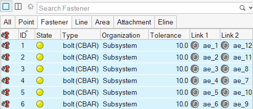
From the Fastener tab of the Connector Browser, select all
of the connectors.
Figure 26. 
- Right-click and select Realize from the context menu.
- From the menu bar, click and save the file as Yaris_BIW_and_Door-REALIZED.hm.