Model Build and Assembly
Tutorial Level: Beginner In this tutorial, you will build and assemble a rails model from CAD to connected FE.
Before you begin, copy the file(s) used in this tutorial to your
working directory.In this tutorial, you will:
- Import the PLMXML file
- Load and create representations
- Load connectors
- Create part sets
- Create configurations
- Realize connectors
- Renumber nodes and elements, run the Model Checker, and export the solver deck
- Work with libraries
Load and Create Representations
- Start HyperMesh with the OptiStruct user profile.
- From the menu bar, click .
- Browse to your working directory, select BOM_input.xml, and click Open.
-
In the BOM Import Options dialog, click
Import.
The Part Browser opens and part assemblies/parts are imported into the session.
-
In the Part Browser, right-click a column name and select
the following check boxes:
- PDM PID
- PDM MID
- PDM Material
- PDM Thickness
- PDM MeshFlag
These columns show the PDM metadata that is parsed upon importation of the PLMXML file. This information is also shown in the Entity Editor, under PDM Data. - Right-click the Frame_Assembly_000495 part and select from the context menu.
-
In the Change Representation dialog, select
CAD and click OK.
All available CAD representations are imported into the session.
Figure 1. 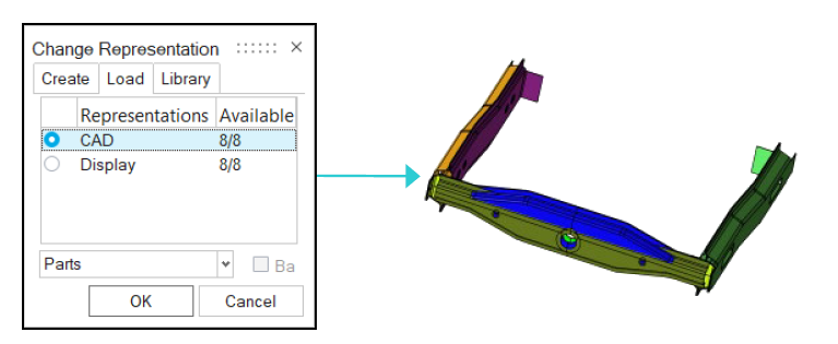
- Right-click the Frame_Assembly_000495 part and select from the context menu.
-
In the Change Representation dialog, select
Common, Durability 5mm, and
NVH 10mm and click OK.
Available CAD representations are sent to BatchMesher for processing.
-
In the BatchMesher dialog, click
Yes to load new representations.
Figure 2. 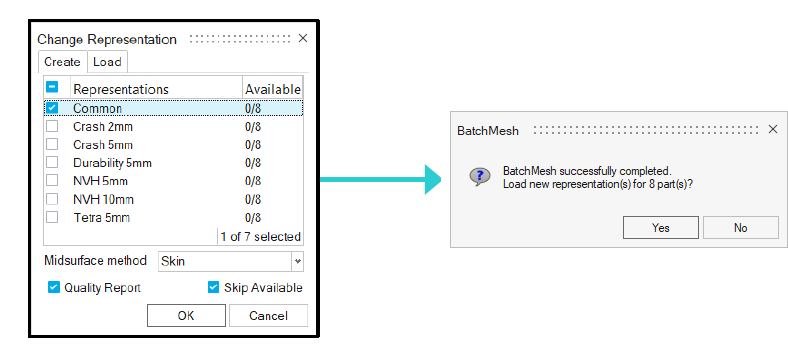
- Right-click on Frame_Assembly_000495 and select from the context menu.
- In the Change Representation dialog, select NVH 10mm and click OK.
- Check the model to see components and properties with correct IDs and thicknesses are created and assigned and match the PDM attributes.
Load Connectors
- From the Part Browser, right-click the Connectors_000481 part and select from the context menu.
-
In the Change Representation dialog, select
Connector and click OK.
Connector groups containing connectors are loaded into their corresponding parts.
Figure 3. 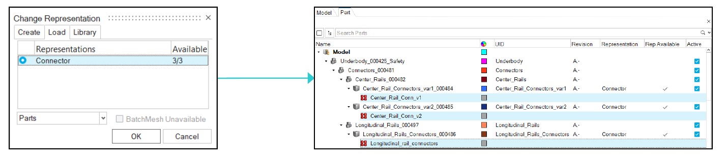
Create Part Sets
-
From the Part Browser, click
 and select
  .
.
- In the Part Sets view of the Part Browser, right-click and select from the context menu.
- In the Entity Editor, enter Var1 as the name.
- Repeat steps 2 and 3 to create a second part set named Var2.
-
Group the following parts by dragging-and-dropping them from the Part view to
the corresponding set.
Part Set Parts Var1 CenterInner_A_000428_Safety CenterOuter_A_000429_Safety
Var2 CenterInner_var2_A_000431_Safety CenterOuter_var2_A_000432_Safety
Figure 4. 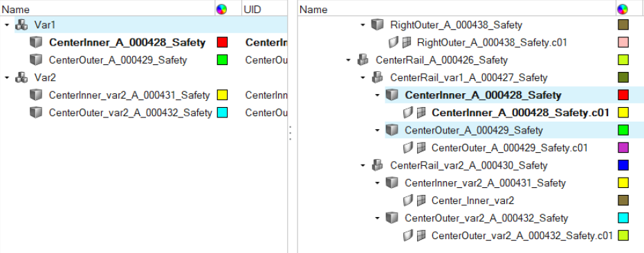
Create Configurations
-
From the Part Browser, click and select
 .
.
- In the Configurations view, right-click and select from the context menu.
- In the Entity Editor, enter Var1 as the name.
- Repeat steps 2 and 3 to create a second configuration named Var2.
-
Group the following part sets by dragging-and-dropping them from the Part Set
view to the corresponding configuration.
Part Set Configuration Var1 Var1 Var2 Var2 -
Select the Active check box for the Var 2
configuration.
Figure 5. 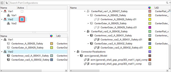
All the parts, part assemblies, components, and part sets not associated with Var2 become inactive.
Realize Connectors
-
From the Connectors ribbon, select the Controls
tool.
Figure 6. 
-
In the Connector Control Manager dialog, click
 .
.
-
Browse to your working directory, select the
controller_defaults.hm file, and click
Open.
Default connector control settings saved to an .hm file mean consistency of realizations across users.
- From the entity selector in the modeling window, select Connectors.
-
In the modeling window, select all connectors in the
modeling window.
Tip: You can press to quickly select all.
- Right-click in the modeling window, select Edit point connectors from the context menu.
-
From the guide bar, select ACM
(General). from the drop-down and click
 .
.
-
In the Part Browser, review the new parts that have been
created to house the realizations.
Figure 7. 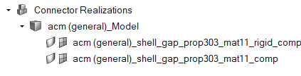
Export Solver Deck
In this step, you will renumber nodes and elements, run the Model Checker, and export the solver deck.
-
From the Assembly ribbon, select the ID
Manager tool.
Figure 8. 
- In the ID Manager dialog, select Component, Area properties, Volume properties, and Material.
- Right-click the selected items and select from the context menu.
- Select and right-click Main Model and select Edit from the context menu.
-
In the Edit dialog, enter 1000000
for Minimum ID and 1500000 for Maximum ID.
Figure 9. 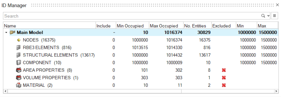
- Click OK.
- Select and right-click Main Model and select from the context menu to renumber the model into the defined range.
-
From the Validate ribbon, select the
Manage Checks tool from the Model tool group.
Figure 10. 
- From the Model Checker, select and right-click ERROR and select Run from the context menu.
-
Verify the model is error free.
Tip: View the Status Bar for additional messages.
- From the menu bar, select .
-
Save the solver deck as frame_var2_assembled.fem and
click Export.
Export of parts is controlled via the write comments for Parts option and are saved to the solver deck via an xml comment block.
Optional: Work with Libraries
-
From the Assembly ribbon, select the
Libraries tool.
Figure 11. 
The Library Manager dialog opens. -
Register a new library.
-
Click
 .
.
- Enter a Library name and Library path.
- Click Add.
-
Click
-
To delete a registered library, select the desired library and click
 .
.
- To connect a library, select a disconnected library and click Connect.
- To disconnect a library, select a connected library and click Disconnect.