Activate the Create Contact option to
automatically generate the contacts between belt and wrap around
components.
Change the 2D Element Size to 10.0.
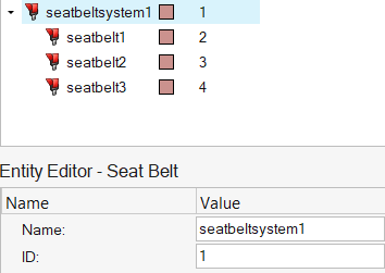
In the Seatbelt Browser, select
seatbelt1 to activate this seatbelt segment.
In the Entity Editor for seatbelt1:
Keep the mesh type of the seatbelt segment to 1D Seatbelt elements
only.
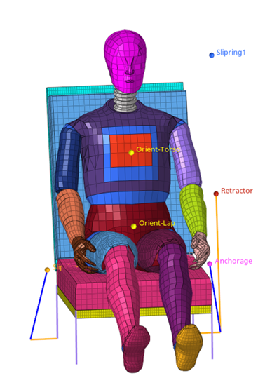
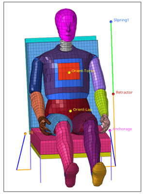
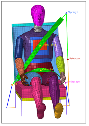
Activate the nodes selector and select the two nodes defined by the
tags "Retractor" and "Slipring1" to define the belt path of
seatbelt1.
The seatbelt1 1D mesh is automatically generated.Figure 5.
In the Seatbelt Browser, select
seatbelt2 to activate the seatbelt segment.
In the Entity Editor for seatbelt2:
Keep the mesh type of the seatbelt segment to 1D & Shell
elements.
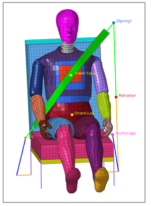
Activate the nodes selector and select the three nodes defined by the
tags "Slipring1," "Orient-Torso," and "Slipring2" to define the belt
path of seatbelt2.
The seatbelt2 mesh is automatically generated.Figure 6.
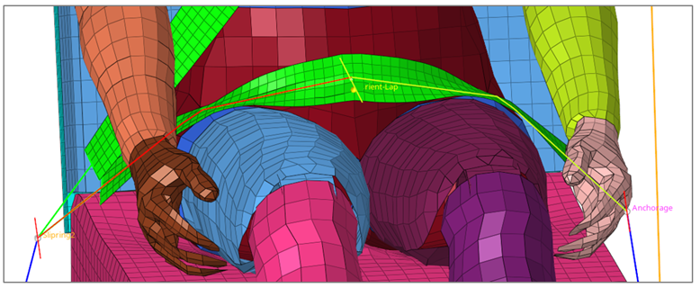
Repeat Step 8 for seatbelt3 by selecting nodes defined by "Slipring2,"
"Orient-Lap," and "Anchorage."
The seatbelt3 mesh is automatically generated.Figure 7.
Interactive Modification of the Belt Path
In this step you will modify the belt path.
In the Seatbelt Browser, select
seatbelt3 and then right-click to open the context menu.
Select Interactive modification.
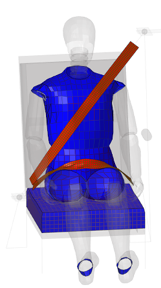
Select the seatbelt line path on the graphic, press and hold the left mouse
button, and move the belt line upward to modify the belt path.
Press Esc to terminate the process.
Figure 8.
Create Solver Seatbelt Entities
In this step you will create solver seatbelt entities.
In the Seatbelt Browser, select the control point named
Point1 in seatbelt1.
Right-click and select Create > Retractor.
Click Create to create an *ELEMENT_SEATBELT_RETRACTOR at
this location.
In the Seatbelt Browser, select the control point named
Point3 in seatbelt1.
Right-click and select Create > Slipring 1D.
Click Create to create an *ELEMENT_SEATBELT_SLIPRING at
this location.
Repeat Step 4 through Step 6 for Point5 to create another Slipring at this
location.
Create Solver Cross-Section on the Seatbelt
In this step you will create a solver cross-section.
In the Seatbelt Browser, select
seatbelt2.
Right-click and select Cross Sections.
Set the Distance from Start and Distance from End to
150.0.
Click Create.
Two cross-sections are generated.
Review Entities Created in the Seatbelt Include File
In this step you will review entities created in the include file.
In the Include view of the Model Browser review the
entities created during the seatbelt creation process.