Tutorial Level: Advanced The goal of this tutorial is to see how head impact simulation following the pedestrian
safety regulation EuroNCAP can be defined using the Pedestrian Impact tool starting from a
full vehicle model.
Pedestrian Impact automates the process with minimal input from you, therefore
reducing the deck generation lead time with less human error.Figure 1.
Model Description
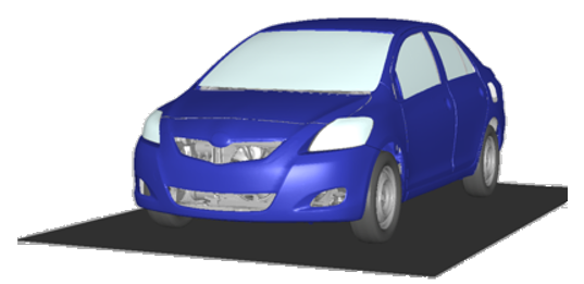
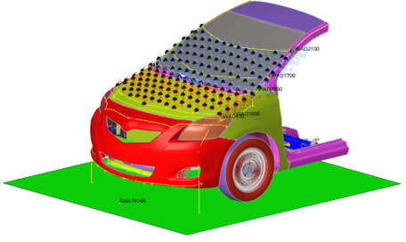
The vehicle model used in this tutorial is based on the free Toyota Yaris model,
provided by the National Crash Analysis Center (NCAC).
The original LS-DYNA model has been converted and validated with Radioss.
Before you begin, copy the file(s) used in this tutorial to your
working directory.
From the Start menu, select Altair (version) > HyperMesh (version).
Select HyperMesh under New Session and then select Radioss for the Profile.
Load the Vehicle Model
From the menu bar, click File > Import > Solver Deck.
Browse and select the vehicle input deck
Toyota_Yaris_0000.rad file located in the Vehicle
folder.
Click Open.
In the Solver Import Options dialog, click
Import.
The model opens in the modeling window.
Open the Pedestrian Impact Tool
From the Safety ribbon, click the
Pedestrian tool.
Figure 3.
Vehicle Marking
In the Vehicle Marking tab, select the inputs for the regulation. For
Regulation select EuroNCAP 8.4 and for Impactor select
Headform.
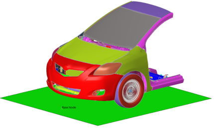
In the Parts selection section, select the different components needed for the
marking process, as shown in the image below.
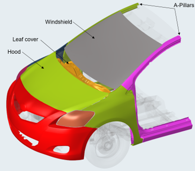
Figure 4. Vehicle Outer Surfaces
For Vehicle Outer select the Hood, Windshield, A-Pillars, Leaf Cover
and headlamps components.
For each single group of components (Hood, Windshield, A-Pillars, Leaf
Cover), select the corresponding components.
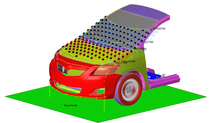
In the Vehicle Inclination section, set the definition of the Ground. For
Ground Type select Flat. For Base node for Z enter
.0.0.
Click Ground plane to see the ground position.
Figure 5.
Click Mark to start the marking process.
Figure 6.
Export Solver Decks for all Impact Points
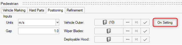
Use the Positioning tab to perform the export of the solver decks for all headform
impact points.
Select and import the headform input deck.
Click On Setting.
Figure 7.
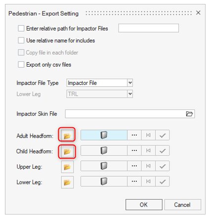
Click the Adult Headform icon and select the
adult headform input deck
Rigid_Adult_Headform_0000.rad located in the
Impactors folder.
Click the Child Headform icon and select the
child headform input deck
Rigid_Child_Headform_0000.rad located in the
Impactors folder.
Figure 8.
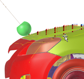
Load and review the headform impactor positioning by selecting an impact point
in the table, and click Preview.
Click YES in the dialog that opens.
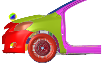
Multiple impact points can be reviewed at the same time. The example below is
for the C_O_O impact position.Figure 9.
Activate the All checkbox in the Export filter
section.
In the Export options section, for the Adult and Child Headform, click the
folder icon and select the respective master files
master_euncap_A-Headform_0000.rad and
master_euncap_C-Headform_0000.rad.
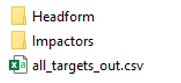
For the Master out directory, click the folder icon and select the
RUNS folder.
Click Export to start the process to export the solver
decks for all of the impact points.
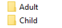
The following folders are created in the RUNS folder:Figure 10. The following folders are created in the Headform folder:Figure 11. In the Adult and Child folders, each of the impact points has its own
folder with the corresponding main file, in which the impactor include file and
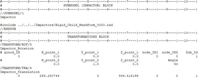
the transformation cards are defined. For example, for the C_0_0 impact point,
here is the data added by the tool in the main file:Figure 12. Each solver deck is ready to be solved by Radioss. Below is an example of the final C_0_0 impact
point input deck:Figure 13.