XenomatiX Scanned Roads
A set of scanned road data from XenomatiX® are available to be used as road models in MotionSolve simulations through the Altair Partner Alliance (APA).
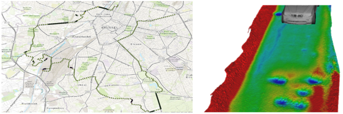
XenomatiX measures and collects precise and up-to-date data of any road network or part of it including local roads, highways, harbor quays, airport runways, or even off-roads. The data is measured using the true solid-state lidar sensor XenoTrack and analyzed in XenoWare road software. Additional information is available at https://xenomatix.com/lidar/road-data.
Accessing XenomatiX Scanned Roads
Sign in to the Altair Marketplace and download the XenomatiX Road Packages (https://altairone.com/Marketplace?app=Xenomatix+Road+Data&tab=Download).
- .crge: Represents the road by an encrypted .crg file.
- .csv: Contains the road centerline to be used in MotionView events.
- .mdl and .h3d: represents the Graphic System and the Road Graphics to be visualized in MotionView and post-processed in HyperView.
License Information
An Altair Partner license is required to use XenomatiX roads with MotionSolve. Please contact mailto:apasupport@altair.com for more information.
How to Use
Prerequisite: A working knowledge of Vehicle modeling and simulation with MotionView and MotionSolve.
- Unzip the downloaded road package.
- Build a full vehicle model.
See Full Vehicle Models with Altair Driver and Events for additional information.
- Add the road file into the model.
The .crge road works similar to the .crg file in the AutoTire and Event Entity Editor.
In the AutoTire Entity Editor, browse and select the .crge file for the Road Property File.
Figure 2. 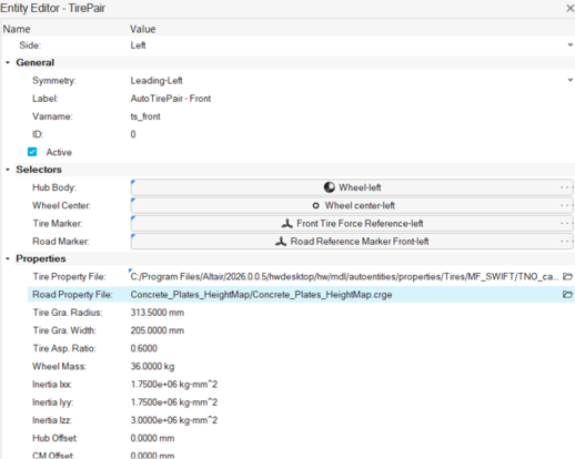
Or in the Event Editor, select Road File under Road Selection.Figure 3. 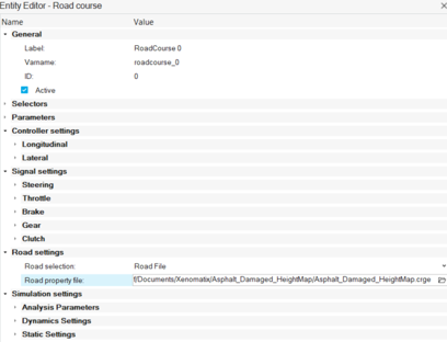
- Import the road graphics.Select the Model and import the .mdl in the road package as a GraphicSystem using File > Import > MDL Definition.
Figure 4. 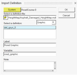
A Road Graphic System is created containing the .h3d with graphics information of the road. Change the graphic_marker attachment of the Road Graphic system to Road Reference Marker Front-left either by selecting the marker in the modeling window window or through Advanced Selector .
.Figure 5. 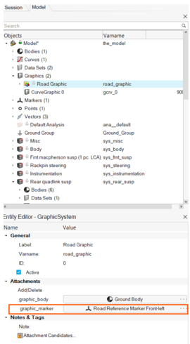
Note: The Road Reference Marker Front-left’s position and orientation might have to be changed to align the road with the vehicle. - Use the road centerline.To use the road centerline in a MotionView event, create a 3D Cartesian Curve entity using the Splines 2D tool under the Model ribbon and select the .csv file within the package.
- Select the Model system.
- Click on the Spline 2D icon in the Model ribbon.
- Click Create and Edit and then Cancel.
- In the Entity Editor:
- Change Curve type to 3D Cartesian.
- Change Data Source for X, Y, and Z to File.
- Select the .csv file in the road package for X, Y, and Z.
- Change Component to Column 2 and Column
3 respectively for Y and Z.
Figure 6. 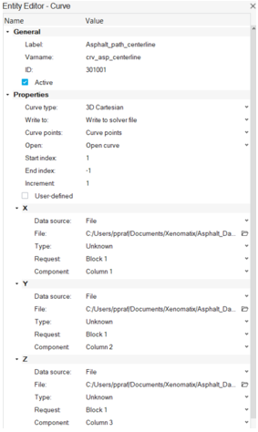
Optional: To visualize the centerline curve, add a Curve graphic using the Graphics tool under Geometry ribbon with the Marker option and use the marker Road Reference Marker Front-Left.
- Add a RoadCourse Event from the Entity Browser under .
- In the Entity Editor, change the Type under Parameters > Path profile to Curve.
- Select the 3D Cartesian curve created in previous step as
Path curve under Curve settings.
Figure 7. 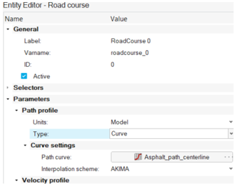
Note: The path curve is interpreted in Road Reference Marker-Front-left coordinate system.
The model is now ready to solve using the XenomatiX road.