Creating a Road Graphic
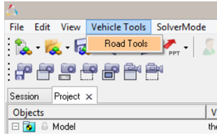
Road Tools can be accessed under the Vehicle Tools menu. *Be sure that you have loaded the Vehicle Tools extension.
The steps to create a road graphic are outlined below.
-
Selecting the road file:
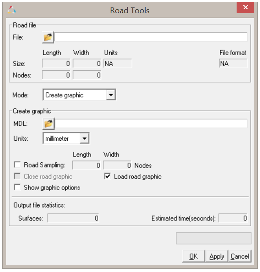
On browsing the input road file path, the road file is parsed to detect the road file type and populate the length and width of the road. The input road file has data points written either in the ASCII or binary format. The parser reads the sampling of file along the length and the width of the road to determine the original data sampling in the input road file.
Figure 3. Road Tools Dialog 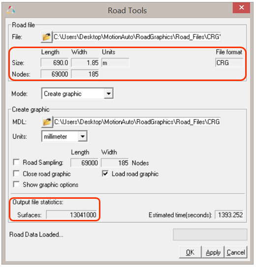
-
Close the road graphic:
Select this option to close the road graphic to form a closed loop. When you select this option the Road Tools evaluate whether the road can be closed. If not, an alert message is displayed.
Figure 4. Graphic entity with the "Close road graphic" option not selected 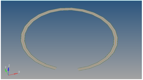
Figure 5. Graphic entity with the "Close road graphic" option selected 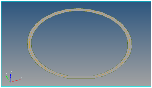
Figure 6. Road Graphic Closure Error message 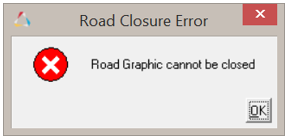
The road closure criterion is based on the following two metrics:- The distance between start and end points is less than 1% of total road length.
- The angle between the starting and ending tangents is less than 40 degrees.
-
Graphic Units:
By default, the graphic units are selected as “millimeter” with respect any input road file units. This option gives you the flexibility to select the output graphic file unit: millimeter, centimeter, meter, kilometer, feet, inch, or mile. The output graphic is thus scaled likewise. All the parameters in graphic options are according to graphic output units.
-
Output File Graphic Sampling:
You can also control the resolution of output file graphic by changing the "Nodes along length” and “Nodes along width” parameters, in order to make a coarse or a fine graphic. By default, the Road Sampling setting generates the output graphic using the same sampling as the input road file.
Figure 7. Road Sampling Settings 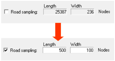
A high number of nodes will result in more elements/surfaces being created in the graphic and would be computationally expensive. For larger files, it is recommended to lower the number of nodes for faster creation of the graphic.Figure 8. Fine mesh/high sampling example 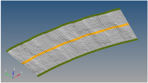
Figure 9. Coarse mesh/low sampling example 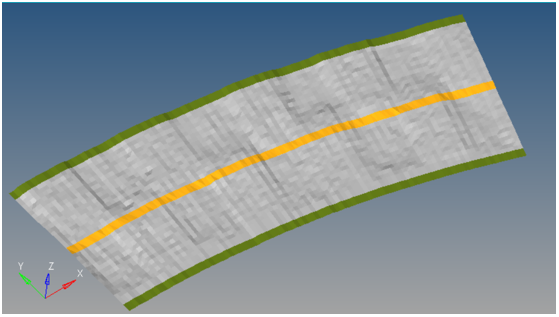
-
Load Road Graphic:
By default, the Road Graphic that is generated is loaded into the active MotionView session. The Load road graphic options provide you with an option to not load the Road Graphic into the model after the creation of the .h3d and .mdl files.
Figure 10. Load Road Graphic 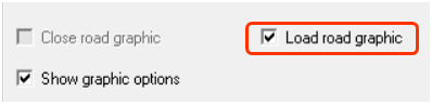
-
Associate with an event/analysis:
Road graphics are typically associated with an event or an analysis. You can associate a road graphic with any existing event/analysis in the model. For example: a rough road event that requires a rough road graphic and an obstacle event that needs an obstacle road. While creating the road graphic you can choose to associate the graphic with an event of your choice by selecting the event in the dialog.
Figure 11. Associate with an Event 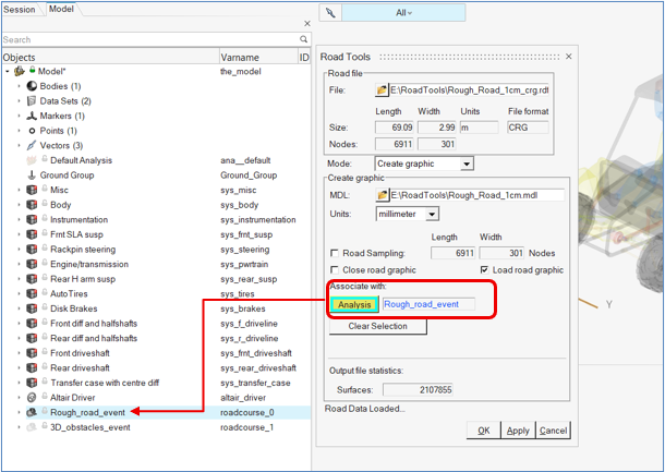
By associating a road graphic with an event, the graphic’s visibility gets associated with the state of the event. That is, the road graphic will be switched ON when the event is activated and vice versa.
Once an event/analysis is selected, if you wish to deselect it, use the Clear Selection button.Note: Limitations of the “Associate” road graphic feature: the association is created during the road graphic creation. If you manually switch ON/OFF the road graphic from the user interface, this association with the event will break and the automatic switching ON/OFF of that particular road graphic will stop. -
Road Graphic Output:
Road Tools is designed as a one click interface to create and load graphics in the active MotionView window. The Graphic Output is loaded as a Graphic System with FileGraphic as its components (road, left shoulder, right shoulder, centerline).
Figure 12. Road Graphic Components 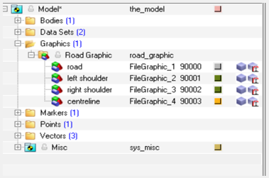
Figure 13. Road Graphic in MotionView 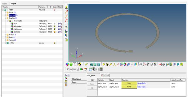
The output graphic is saved as a Graphic System of file graphic in a MotionView .mdl file. By default, the output graphic model is saved in the same working directory as the input road property file and has the same file name with a .mdl extension. You do however have the option to change this destination by changing file path in the output graphic path.
The Output graphic has two attachments, “graphic body” and “graphic marker” to seamlessly integrate the road graphic into existing models. By default, the graphic body is resolved to the Ground Body and the graphic marker is resolved to the road marker, if it exists, or to the Global Frame if it does not.Figure 14. Road Graphic System Attachments 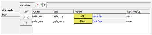
-
Reusability of a Road Graphic:
The saved output graphic file is in the the MotionView .mdl format with a Graphic System definition (see *DefineGraphic() for additional information). This can be imported and reused in any other model that requires the same road graphic.