
Fillets
Create fillets or chamfers along an edge.
Fillet Edges
Round edges to create fillets with a constant or variable radius.
-
On the Geometry ribbon, select the
Fillet Edges tool.

Tip: To find and open a tool, press Ctrl+F. For more information, see Find and Search for Tools.The guide panel appears.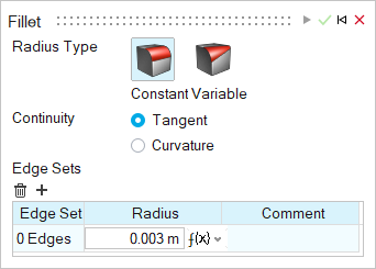
-
Choose a Radius Type:
- Constant: Create fillets with the same radius for every edge.
- Variable: Create fillets with a variable radius at selected points along the edges.
-
Choose a Continuity type:
- Tangent: Force tangent (G1) continuity along the edge.
- Curvature: Force curvature (G2) continuity along the edge.
-
Create and modify edge sets:
To Do this Add an edge set - Click the + button and select the edges.Tip: In the microdialog, select Tangent Propagation so that clicking an edge will also select all of its tangent edges.
To select all of the boundary edges of a face, click the face.
- You can adjust the Radius for each edge set.
Delete the current edge set Under Edge Sets, click  .
. - Click the + button and select the edges.
-
Create a modify points (Variable radius only):
To Do this Add a point where the radius varies Click along the edge. Delete selected points - Under Points, click .
- Alternatively, in the modeling window, select a radius handle and press Delete.
Modify the point’s position along the edge Enter a value from 0 to 1, where 0 and 1 correspond to the edge’s endpoints and 0.5 corresponds to the mid of the chain. You can also select the radius handle and drag it along the edge. - Under Points, click
-
Click Apply.
Features are automatically retained and notches are preserved on sheets.
- Right-click and mouse through the check mark to exit, or double-right-click.
Tip:
- By default, clicking an edge will also select all of its tangent edges.
Deselect Tangent Propagation
 in the microdialog to
disable this behavior.
in the microdialog to
disable this behavior. - If the fillet radius text box is highlighted red due to an invalid edge selection, press Ctrl+Z to undo or press Ctrl while clicking to deselect the edge. The previously valid selection will reappear.
- Change the default fillet radius in the Preferences.
Chamfer Edges
Create beveled edges.
-
On the Geometry ribbon, select the
Chamfer Edges tool.

Tip: To find and open a tool, press Ctrl+F. For more information, see Find and Search for Tools. -
Select edges to chamfer.
- To select an edge, click the edge.
- To select multiple edges, use box selection or press Ctrl while clicking the edges.
- To select all of the boundary edges of a face, click the face.
-
Choose from the following options:
- Distance, Angle: Enter a horizontal distance and an angle.
- Distance, Distance: Enter a horizontal distance and a vertical distance.
If you entered an invalid value, the text box is highlighted in red.
Note: The values you enter will be automatically applied to all selected features. -
Select Apply
 on the microdialog.
Features are automatically retained and notches are preserved on sheets.
on the microdialog.
Features are automatically retained and notches are preserved on sheets.
Tip:
- By default, clicking an edge will also select all of its tangent edges.
Deselect Tangent Propagation in the microdialog to
disable this behavior.
- Reverse the side the distance and angle are measured from by clicking
 in the microdialog.
 - If a distance/angle text box is highlighted red due to an invalid edge selection, press Ctrl+Z to undo or press Ctrl while clicking to deselect the edge. The previously valid selection will reappear.
- Change the default chamfer distance and angle in the Preferences.
Create or Assign Variables to Parametrize a Model
Create or assign variables to parametrize a model. Variables can be created from a tool or the tool’s microdialog where f(x) is present.
You can create or assign existing variables via the microdialog or in various tools and contexts.
Keyboard Shortcuts & Mouse Controls
| To | Do this |
|---|---|
| Select features | Click |
| Append/remove feature selection | Ctrl+click |
| Delete selected feature | Delete+click |
| Delete selected filleted/chamfered face | Delete |
| Exit tool | Right-click and mouse through the check mark to exit, or double-right-click. |