
Blend Curve
Create a free-form curve that blends into one or more existing curves, surfaces, or edges.
Unlike a NURBS curve, a blend curve passes through the points.
Blend points can be attached to objects so that when the source object is updated, the blend curve is updated as well.
-
On the Geometry ribbon, select the Blend tool.

Note: The tool may be hidden in the dropdown menu. To access the dropdown menu, you can do one of the following:- Select
 at the lower right corner of the
currently displayed tool.
at the lower right corner of the
currently displayed tool. - Click and hold the currently displayed tool.
Tip: To find and open a tool, press Ctrl+F. For more information, see Find and Search for Tools. - Select
- Optional:
In the guide bar, select a curve degree. This controls the placement of the
points to determine the shape of the blend curve.
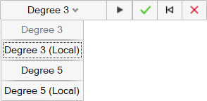
- Degree 3: Create a degree 3 curve. Modifying a point on the curve can affect the entire curve.
- Degree 3 (Local): Create a degree 3 curve with local interpolation. Modifying a point on the curve affects only the sections of the curve adjacent to that point.
- Degree 5: Create a degree 5 curve. In general, select this option to produce a smoother curve. Modifying a point on the curve can affect the entire curve.
- Degree 5 (Local): Create a degree 5 curve with local interpolation. In general, select this option to produce a smoother curve. Modifying a point on the curve affects only the sections of the curve adjacent to that point.
- To place the points, click existing vertices, sketch points, reference points, or free space.
-
To edit points during creation, click the
 in the microdialog to expand it and
type values in the X, Y, or
Z boxes to fine-tune each point's coordinates. To add
a variable to any coordinate, select the
in the microdialog to expand it and
type values in the X, Y, or
Z boxes to fine-tune each point's coordinates. To add
a variable to any coordinate, select the 
icon.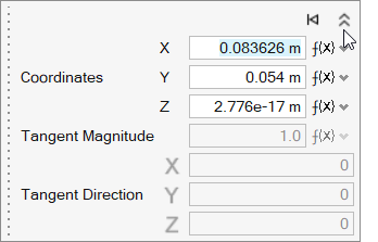
Tip:- To reset the curve to automatic tangent behavior, click
Auto Tangent
 .
. - To set the tangent direction Z to be double the X value, enter 1 in the X value and 2 in the Z value.
- To suspend snapping, hold Alt. You can then move the point freely along its current face or
edge.
Figure 1. Suspend Face Snapping 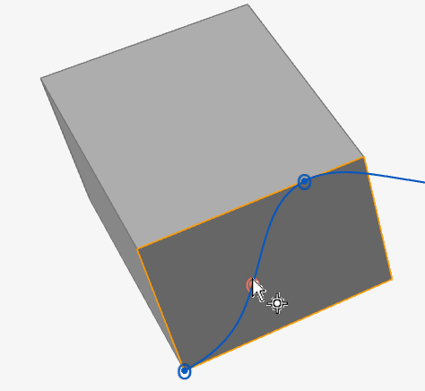
Figure 2. Suspend Edge Snapping 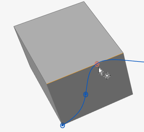
- Press Esc to clear the current curve and exit the tool. Click
Reset
 in the microdialog to
clear the current curve without exiting the tool.
in the microdialog to
clear the current curve without exiting the tool.
- To reset the curve to automatic tangent behavior, click
Auto Tangent
-
To edit after creation, right-click the blend curve in the History Browser
(F6), and then select
Edit.
To Do this Reposition a point - Drag the point.
- Click the point. In the microdialog, click the chevron, and then enter the X, Y, and Z coordinates.
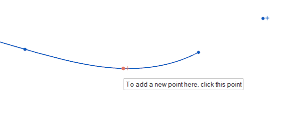
Add a point - To extend the blend curve, click the plus sign near
an endpoint.
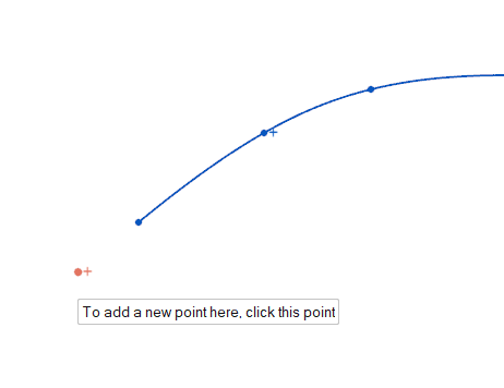
- To insert a point on the blend curve, click a plus
sign.
Delete a point Click the point, and then press Delete. Change the curve degree The curve degree controls the placement of the points to determine the shape of the blend curve. In the guide bar, select one of the following options:
- Cubic (3): Create a degree 3 curve.
- Quintic (5): Create a degree 5 curve. In general, select this option to produce a smoother curve.
Change the continuity The continuity is used to constrain the shape of the curve at a selected point. Click a point. In the microdialog, select one of the following options:
- Position (G0) (default): The blend curve is merely attached to the curve or surface at the blend point.
- Tangent (G1): The blend curve is made tangent to the curve or surface at the blend point.
- Curvature (G2): The blend curve follows the curvature of the attached curve or surface. The curvature is the same on both sides across the blend curve's boundaries.
- Double Curvature (G3): Only available if you selected Quintic (5) for the Degree. The blend curve follows the curvature of the attached curve or surface. The curvature's rate of change is the same on both sides across the blend curve's boundaries.
Change the tangent magnitude of a point Click a point. In the microdialog, click the chevron, and then enter the Tangent Magnitude. Break the link between the point and the snap point Click the point. In the microdialog, select  Break Snap
Reference. Click the icon to link a selected
feature to a snap reference point. Click it again to break
the snap reference.
Break Snap
Reference. Click the icon to link a selected
feature to a snap reference point. Click it again to break
the snap reference.Link the point to a snap curve The shape of the blend curve will change based on the position of the snap point. Click the point. In the microdialog, select
 Maintain Snap
Reference.
Maintain Snap
Reference.Automatically calculate the best tangent direction Click the point. In the microdialog, turn on Auto Tangent. - Right-click and mouse through the check mark to exit, or double-right-click. The curve is in edit mode.