Tutorial 9: Combustor Model
Purpose/Objective
This exercise will walk the user through building a combustor model. The user will learn how to:
- Edit chamber properties
- Edit element properties
- Check the model
- Run the model
- Post-process the model
- Chamber Types: Plenum, Momentum
- Element Types: Standard Tube, Conventional Orifice, Simple Diffuser, Cp – Arbitrary Ref. Chamber (Diffuser), CEA Combustion Element, Fuel Source
- Fluid: Air, Fuel
Step 1: Examine geometry and create plan
- The user will be creating a model of a combustor as shown in figure 1.01. The
combustor mixes fuel with the compressed air to generate energy that will power the
turbines and provide high velocity gas to exit the engine. This is an example model
of how to generate a combustion model.
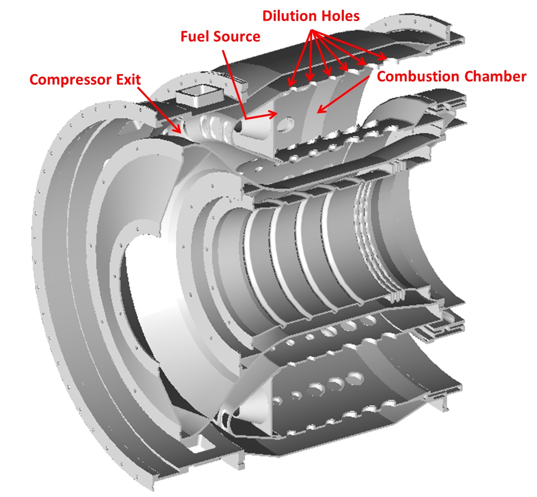
Figure 1.01: Combustor
- Compressor air flows through the inlet of the compressor and on the outside of the
combustor liner. Compressor air will enter the combustion chamber through the
dilution holes. (shown in Figure 1.02)
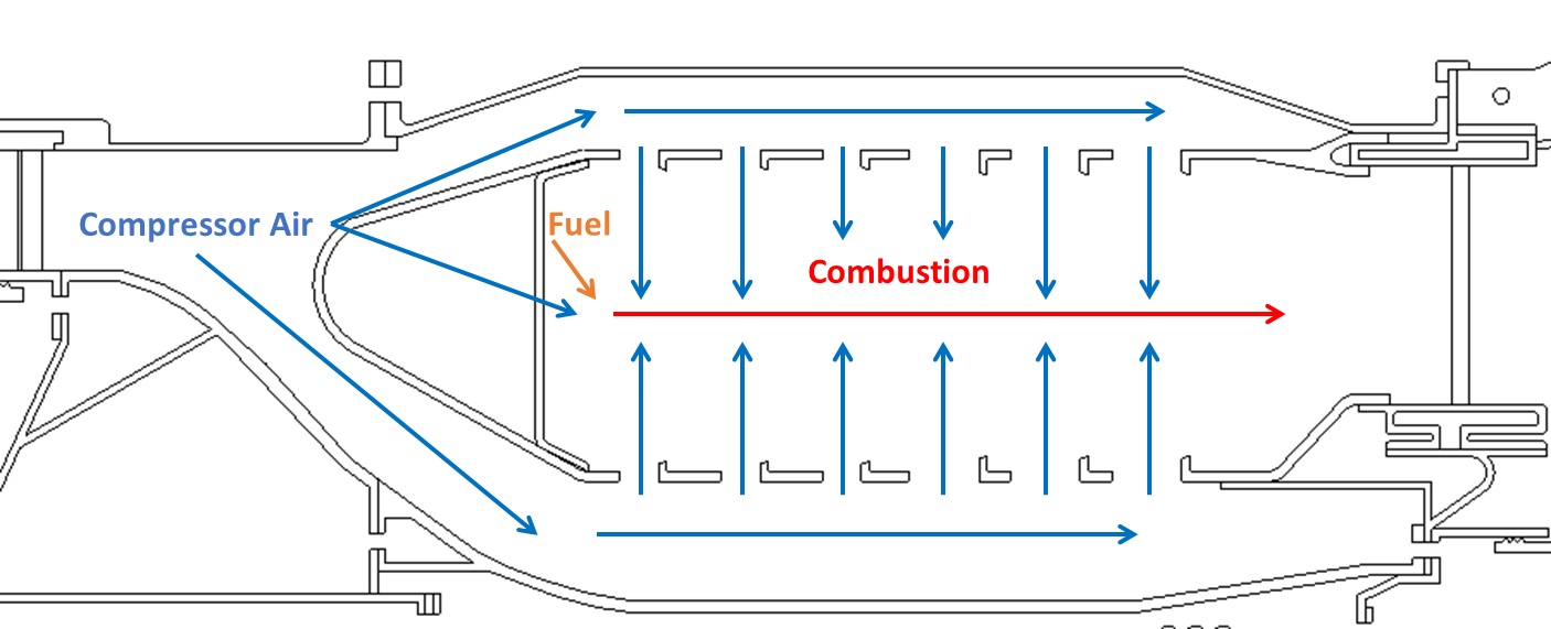
Figure 1.02: Cooling air flow path
- To model compressor air, the user will be making use of tube, conventional orifice, and diffuser elements.
- To model combustion, the user will be making use of the fuel source, CEA combustion and tube elements.
Step 2: Load IGES file
- Go to File → Load IGES File
- Browse to IGES location and select open (engine_cross_section.igs)
- Go to File → Load IGES File
- Browse to IGES location and select open (combustor_3d.igs)
- Loading in these IGES Files separately will give you the ability to independently
hide the 3D or 2D models.
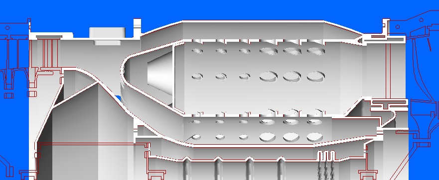
Figure 1.03: Loaded IGES file
Step 3: Building Model
- Plan model setup based on what is known about the geometry
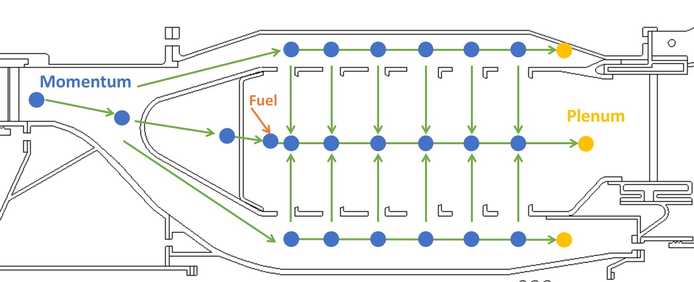
Figure 1.04: Sketch/Outline of Combustor Flow
- Drag and drop Boundary Momentum chamber at the inlet and 3 boundary plenum chambers at the outlet locations from Figure 1.04
- Drag and drop Internal Momentum chambers up to the first set of dilution holes. An intermediate momentum chamber will need to be generated between the combustion element and tube element as the tube element will be used to capture any area change. Seen in Figure 1.05
- Use
 to adjust symbol and text size
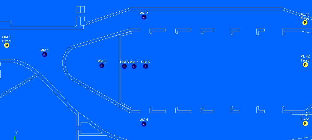
Figure 1.05: Initial Chamber Set-Up
- Next generate the simple diffuser between the inlet and the downstream momentum
chamber
- Set Cp to 0.5
- Set Inlet Area to 55.8 in^2
- Set Exit Area to 84.2 in^2
- Generate the outer Cp – Arbitrary Ref. Chamber (Diffuser)
- Set Cp to 0.6
- Set Exit Area to 39.5 in^2
- Cham for Pressure Recovery 1
- Set Target Flow to 20 lb/s. Target flow was estimated for this model based upon the flow split you would expect to see in a combustor. Outer flow was set lower due to a lower expected flow in the outer circuit.
- Generate the inner Cp – Arbitrary Ref. Chamber (Diffuser)
- Set Cp to 0.6
- Set Exit Area to 30.5 in^2
- Cham for Pressure Recovery 1
- Set Target Flow to 27 lb/s. Target flow was estimated for this model based upon the flow split you would expect to see in a combustor. Inner flow was set higher due to a higher expected flow in the inner circuit.
- Generate first inlet Conventional Orifice
- Set Area to 12.48 in^2
- Set CD to 1
- Generate second 2nd inlet Conventional Orifice (Models main air inlet to
combustion chamber)
- Set Area to 0.4868 in^2
- Set CD to 1
- Set Hide Advanced Options → Element Multiplicity → No. of Streams Entering and Exiting to 24
- Generate second 3rd inlet Conventional Orifice (Models cooling holes for
metal surface)
- Set Diameter to 0.05 in
- Set CD to 1
- Set Hide Advanced Options → Element Multiplicity → No. of Streams Entering and Exiting to 200
- Add fuel source to first momentum chamber in the combustion chamber
- Set static pressure to 380 psi
- Set fuel temperature to 100 F
- Set fuel flow to 2 lb/s
- Generate a tube element between chamber 7 and chamber 8
- Set number of stations to 5
- Set area to 125.2 in^2
- Set length to 0.76 in
- Set Hide Advanced Options → Heat Addition → Wall Temperature to 2000F. The 2000F is an estimate of the average metal temperature surrounding the tube. A more accurate method would be to create a thermal network to model the heat transfer.
- Generate an orifice between chamber 3 and chamber 8
- Set Diameter to 0.4 in
- Set CD to 0.8
- Set Hide Advanced Options → Element Multiplicity → No. of Streams Entering and Exiting to 18
- Set Hide Advanced Options → Element Orientation → Element Inlet Orientation to Radial Inward
- Generate an orifice between chamber 4 and chamber 8
- Set Diameter to 0.4 in
- Set CD to 0.8
- Set Hide Advanced Options → Element Multiplicity → No. of Streams Entering and Exiting to 18
- Set Hide Advanced Options → Element Orientation → Element Inlet Orientation to Radial Outward
- See initial element set-up in Figure 1.06
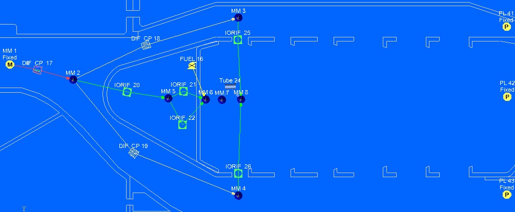
Figure 1.06: Initial Element Set-Up
- Select and Copy the tube and orifices that model the dilution holes and combustion
chamber
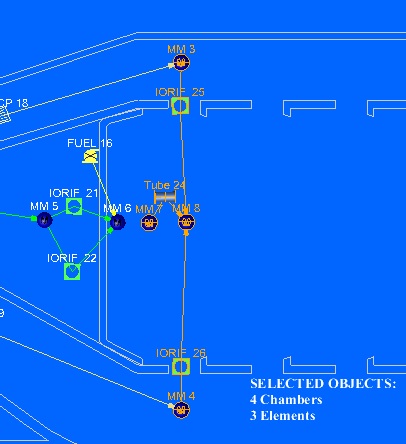
Figure 1.07: Subset of Entities to Select and Copy
- Copy this subset and place until all dilution holes are modeled.
- Figure 1.08 shows the finished copied elements
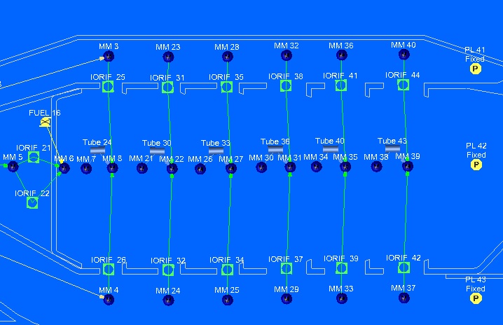
Figure 1.08: Completed element copy
- Select the last 3 orifice elements on the outer and inner separately and update the
area as these are bigger holes.
- Set Area to 0.2 in^2
- Select each tube element and update the length
- First tube, Set length to 0.76 in
- Second and Third tube, set length to 0.63 in
- Fourth tube, set length to 0.47 in
- Last two tubes, set length to 0.31 in
- Generate tube elements between the outer dilution holes
- Set number of stations to 5
- Set area to 39.5 in^2
- Set Hide Advanced Options → Heat Addition → Wall Temperature to 1500F
- Set length on first two tubes to 0.63 in
- Set length of third tube to 0.47 in
- Set length of last two tubes to 0.31 in
- Generate tube elements between the inner dilution holes
- Set number of stations to 5
- Set area to 30.5 in^2
- Set Hide Advanced Options → Heat Addition → Wall Temperature to 1500F
- Set length on first two tubes to 0.63 in
- Set length of third tube to 0.47 in
- Set length of last two tubes to 0.31 in
- Generate combustion elements in the combustion chamber
- Set area to 125.2 in^2
- Generate Fixed Flow elements leaving the outer, inner and combustion chamber
- Set outer flow to 5 lb/s
- Set combustion chamber flow to 60 lb/s
- Set inner flow to 12 lb/s
- See Figure 1.08 for finished model
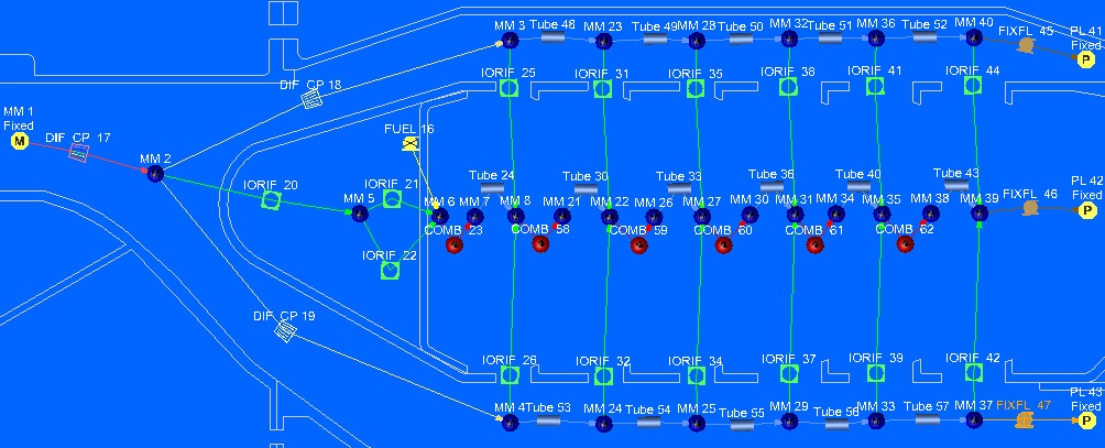
Figure 1.08: Finished model layout
- Set inlet Boundary Momentum Static Pressure to 375 psi, Total Pressure to 400 psi, and Temperature to 1000 F
- Set outlet Boundary Chambers Static Pressure to 370 psi
- Set inner and outer circuit to 1000F
- Set combustion exit to 3000F
Step 4: Check Model and Run
- Select
 , then select working fluid, and set
- Select checkmark icon from the top toolbar
 to check the model for warnings/errors.
- An error should populate stating that the internal chamber has not been initialized
- Select the initialization icon from the toolbar
 , and pick Start. Accept values once flow
solver has converged.
, and pick Start. Accept values once flow
solver has converged. - Select run icon from toolbar
 . Run Flow Simulator.
Step 5: Post-process
- Results file (*.res) should automatically be loaded into GUI. If not, it can be selected via File → Load Result File
- By default, both chamber and elemental results are displayed in the graphical
workspace.
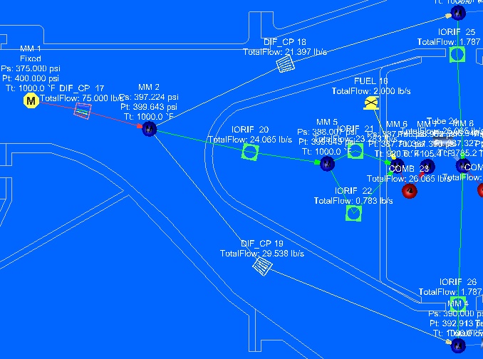
Figure 1.09: Subset of Flow Model Results
- For combustion models, you can see where combustion is taking place by using the
Contour plot. Click
 On the right hand side, Select total
temperature and result data. Then select
On the right hand side, Select total
temperature and result data. Then select 
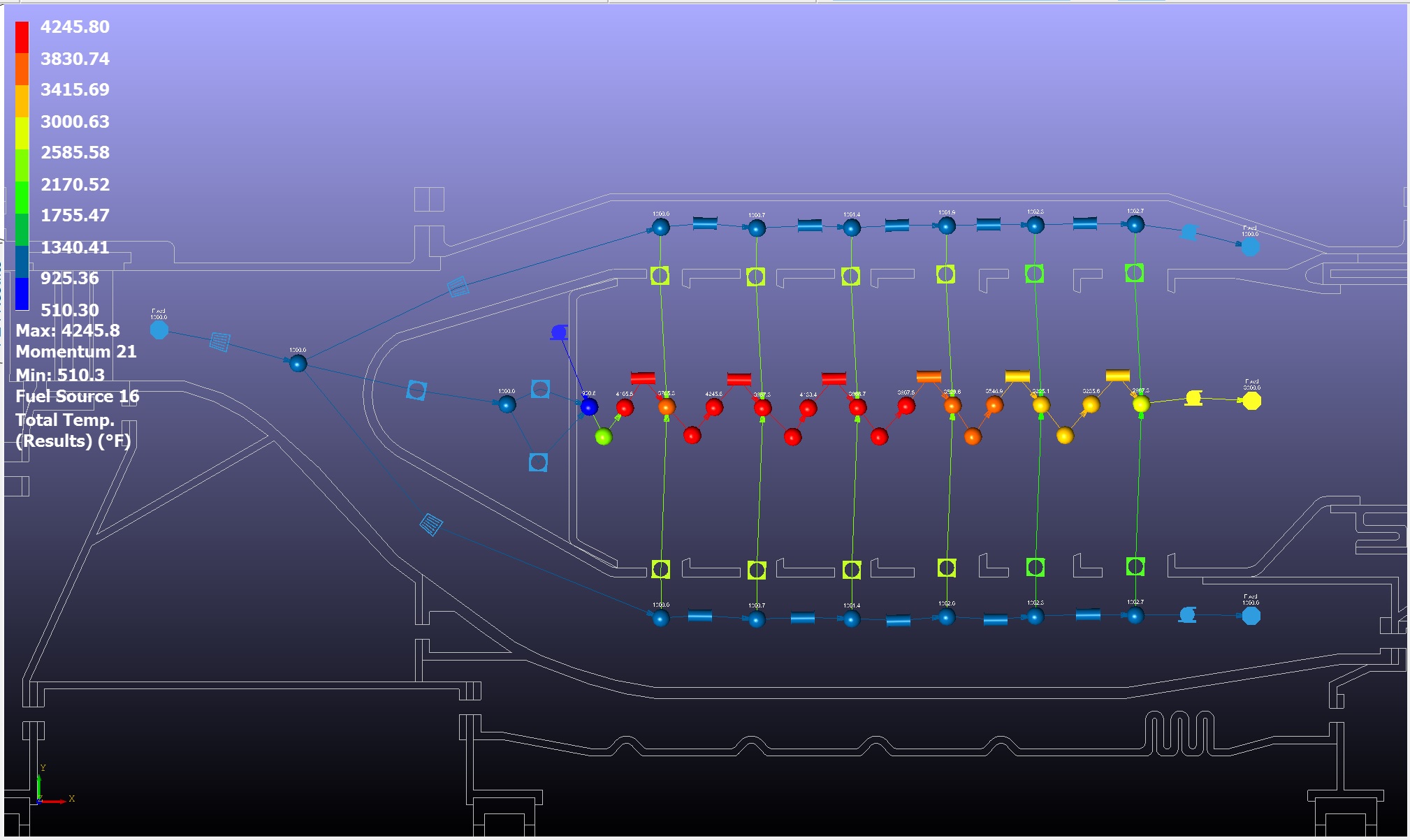
Figure 1.10: Model Temperature Results
- This will allow you to see where most of the fuel is being combusted.