Tutorial 2: Piping System
In this exercise, you will learn how to build a portion of a piping system's water
circuit. The steps include:
- Use CAD to create elements.
- Edit chamber properties.
- Edit element properties.
- Check the model.
- Run the model.
- Post-process the model.
- Chamber Types: Plenum, Momentum.
- Element Types: Junctions, Incompressible Tube, Bends, Transition.
- Fluid: Liquid Water.
Step 1: Examine the geometry and create a plan
Create a model of a water piping circuit shown in Figure 1.
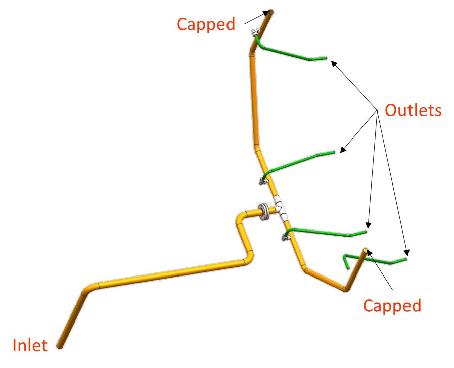
- The model begins with long runs of straight piping connected by 90 degree bends. It then splits in two directions and transitions into smaller diameter pipes, which feed four spray nozzles.
- To model this piping system, use the tube, bend, and junction elements.
- Use CAD to make most of the tubes and bends. The junctions are made manually. The elements around the junctions must be reconnected to the junctions.
Step 2: Load the IGES file
- Go to .
- Browse to the IGES location and select and open
water_piping.igs.
Figure 2. Loaded IGES on default background 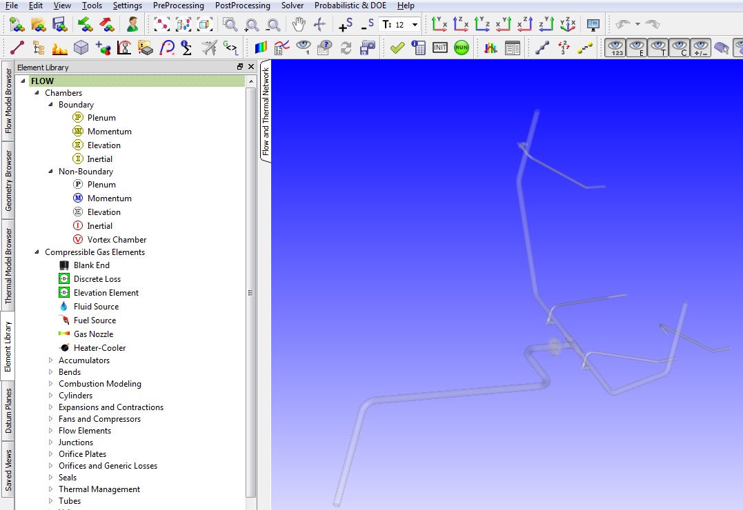
Step 3: Build the model
- Plan the model setup based on what is known about the geometry.
Figure 3. Sketch/outline of model 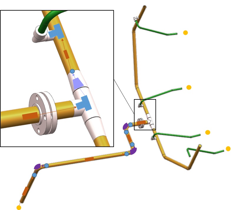
- Create tube and bend elements using the CAD geometry. Most of the tubes and bends
can be made quickly using the CAD. This method creates internal momentum chambers
for all elements, which you can change later. The main geometric inputs for the
tubes and bends are calculated by the GUI when using this option.
Figure 4. Menu options 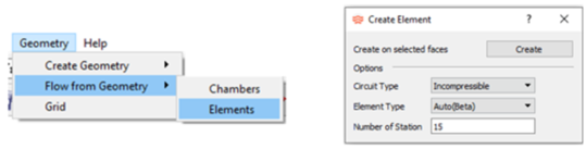
Figure 5. Element creation using CAD 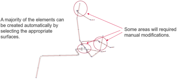
- Use
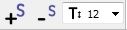 to adjust the symbol and text size.
 - Change the boundary chambers from internal momentum chambers to boundary plenum chambers.
Figure 6. Locations of the boundary plenum chambers 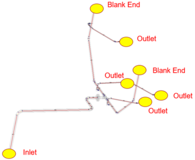
- Set the inlet plenum to a static pressure of 24.7 psi and a relative total
temperature of 70℉.
Set Material to water.
- Set the outlet plenums and blank end plenums to a static pressure of 14.7 psi and a
relative total temperature of 70℉.
Set Material to water.
- Use multiple-edit to change the surface roughness of all incompressible tube elements to 0.0018 in. Do the same for the bend elements.
- Click and drag incompressible T-Junction elements to the pipe connection locations
shown in Figure 7.
Press Alt and pick surfaces close to the locations. Details
about creating the center junction are shown in Figure 8:
Figure 7. T-Junction locations 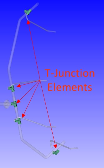
Figure 8. Center junction details 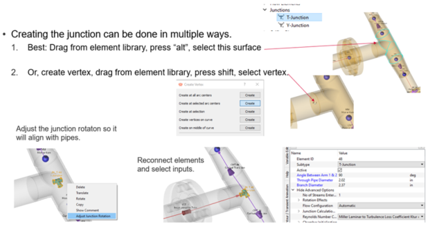
- Set up the spray nozzle as shown in Figure 9.
Figure 9. Nozzle model setup 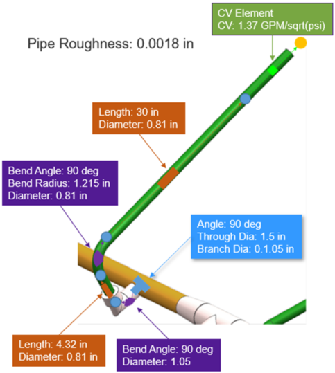
- You created the tube and bend elements earlier. Change the last tube to a CV element
with CV=1.37 and FL=1.
Figure 10. Connect nozzle arms 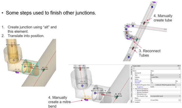
- One of the elbows leading to the nozzle is missing. Use the
Translate option to copy elements from a finished elbow
to this location.
Figure 11. 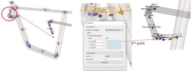
Figure 12. Use Blank End to cap the model 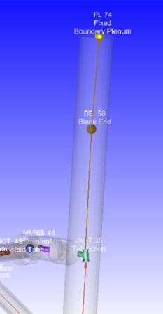
Step 4: Check and run the model
- To check the model for warnings/errors, select the check mark icon from the top
toolbar,
 .
.An error is displayed, stating that the internal chamber has not been initialized.
- From the toolbar, select the initialization icon,
 , and click Start. Accept values
once the flow solver has converged.
, and click Start. Accept values
once the flow solver has converged. - From the toolbar, select the run icon,
 . Run
Flow Simulator.
. Run
Flow Simulator.
Step 5: Post-process
- The results file (*.res) automatically loads into the application. If not, use to select it.
- By default, the graphical workspace displays both chamber and elemental results.
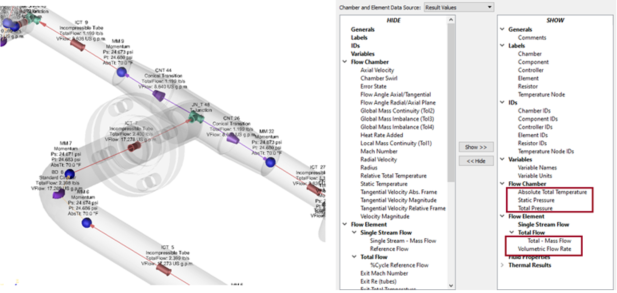
- Use to customize the displayed results.Display the flow in GPM and the static pressure.
Figure 13. Results near Junction 1