Tutorial 10: Probabilistic Tutorial
Purpose/Objective
This exercise will walk the user through setting up a probabilistic run. The user will learn how to:
- Use Flow Simulator Probabilistic tool
Step 1: Objective
- The user will start with the existing S1B supply model and set up a probabilistic run to investigate the effects on swirl caused by changes in angle and area of an upstream element
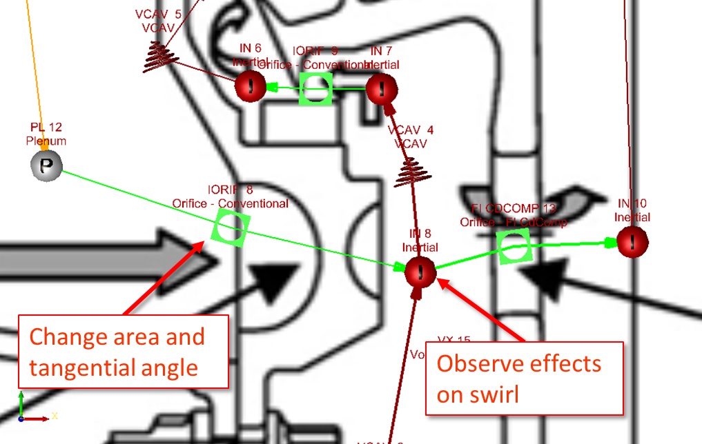
Figure 1.01: Element and chamber of focus
Step 2: Load existing model
- Browse to model location and select open (Probabilistic_start.flo)

Figure 1.02: Loading existing model
Step 3: Building Model
- Go to Probabilistic & DOE → Probabilistic
Figure 1.03: Probabilistic menu
- Set Number of Runs to 20
- Add the first input
- Under Group, select Element
- Set ID to the Element ID upstream of the chamber of focus
- Set Property to Tangential Angle
- Set Dist. Type to Uniform
- Enter a Lower Bound and Upper Bound of 60 and 80 respectively
- Click Add Input (this adds another line)
- Under Group, select Element
- Set ID to the Element ID upstream of the chamber of focus
- Set Property to Area
- Set Dist. Type to Uniform
- Enter a Lower Bound and Upper Bound of 0.04 and 0.05 respectively
- Click Generate Table & Save Multicase File and name it
table_angle_area.txt
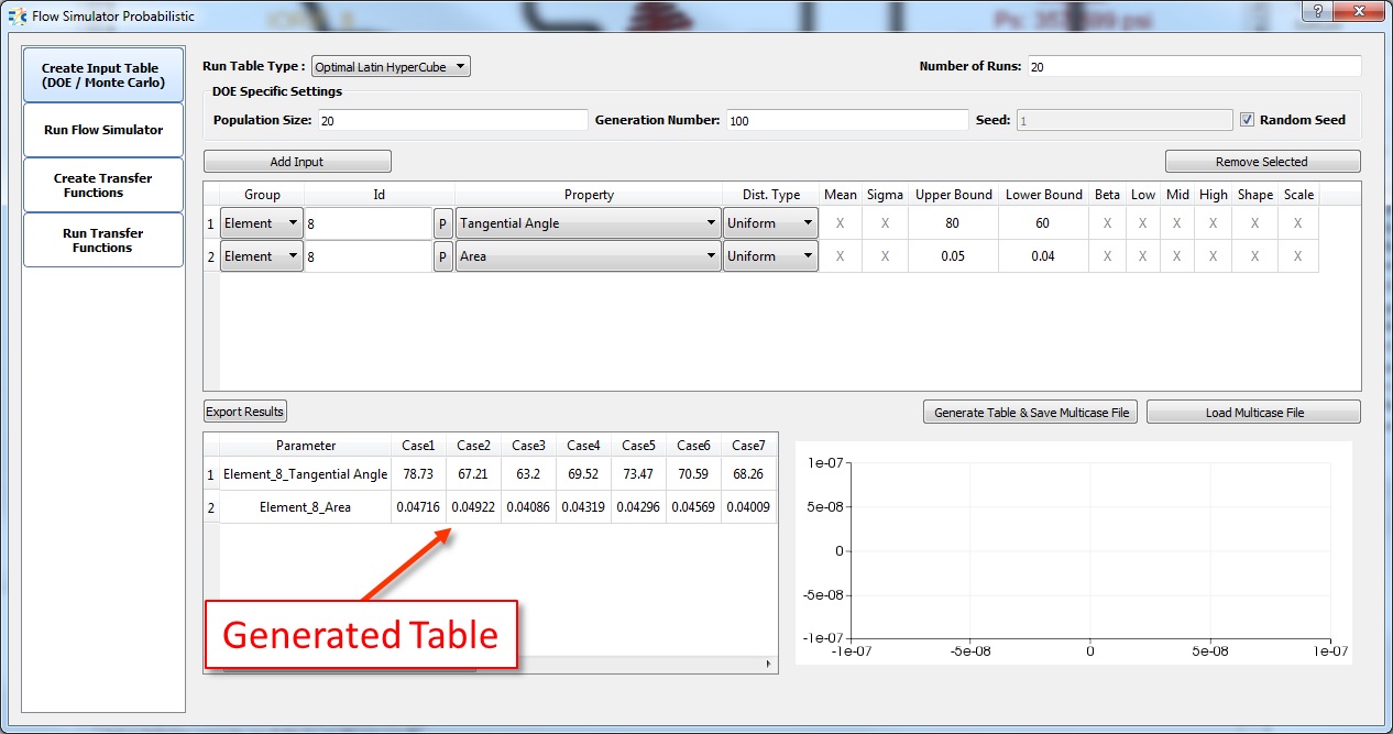
Figure 1.04: Generated table of tangential angle values
- Go to Solver → Analysis Setup → Solvers Convergence and set Maximum Number of Iterations to 500 and Save
- Under the Run Flow Simulator tab, click the “…” at the end of Run Table line and
browse to the table_angle_area.txt file created earlier
Figure 1.05: Generated table of tangential angle values

- Click Run Flow Simulator
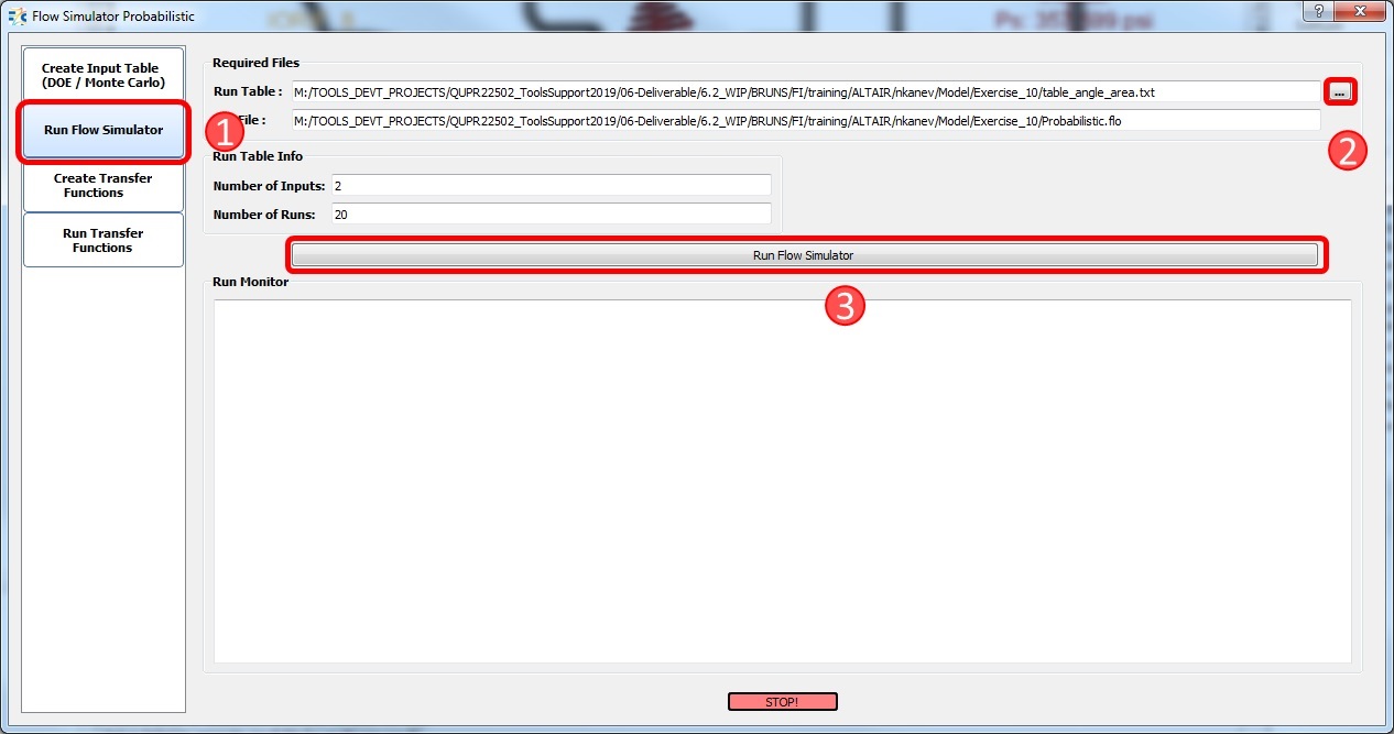
Figure 1.06: Readout of run cases
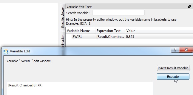
- Create a Variable in the Variable Edit Tree for the Transfer Function
- Go To PreProcessing → Model Parameters → Variable Editor
- Right Click in Variable Edit Tree and click Add Variable
- Name the Variable SWIRL
- Right Click on the Variable Name SWIRL and select “Set Expression”
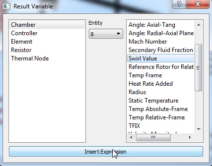
- Click “Insert Result Variable”
- Select Chamber, 8, Swirl and then Insert Expression
- Click “Execute”
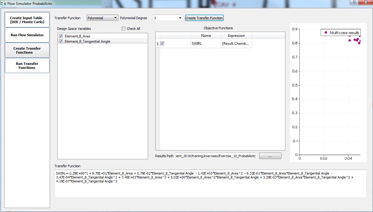
- Click “Create Transfer Functions” in the Flow Simulator Probabilistic Window
- Set inputs as shown below and click “Create Transfer Function”
- The Transfer Function Equation is the relationship between the element area and angle to the downstream chamber swirl.
- Set inputs as shown below and click “Create Transfer Function”
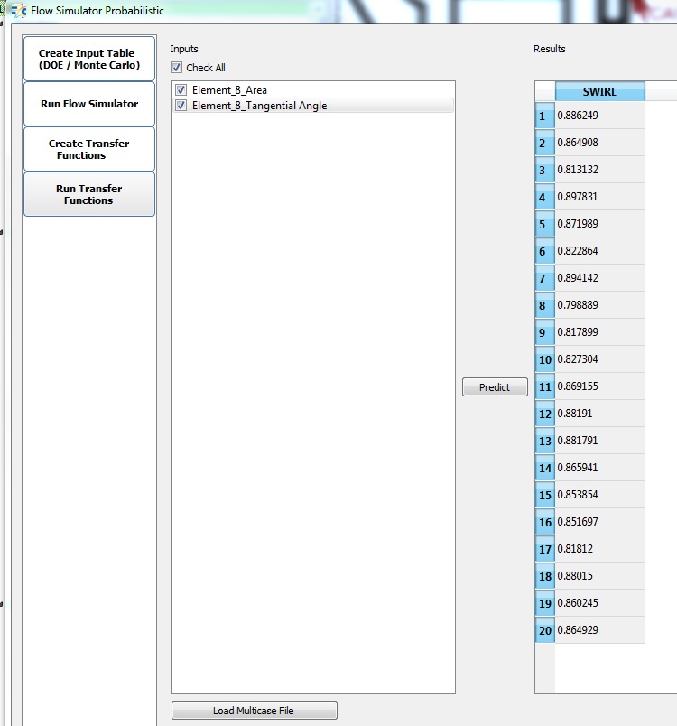
- Click “Run Transfer Functions” in the Flow Simulator Probabilistic Window
- Click “Check All” and “Predict”
-
This shows the results of the trasfer function equation for each of the 20 cases run.
- Click “Check All” and “Predict”
- Another Way to Post Process: Go to PostProcessing → Results Table
- Under Results, click
 , select the Elements radial
button and enter the element ID of the element with varying tangential angle
, select the Elements radial
button and enter the element ID of the element with varying tangential angle - Select Append and go to the Inputs tab
- Choose Tangential Angle (EL_THETA,22)
- Choose Area (area, 202)
- Select and choose the chamber downstream of the
changed element
- Select Append and go to the Results tab
- Choose Swirl Value
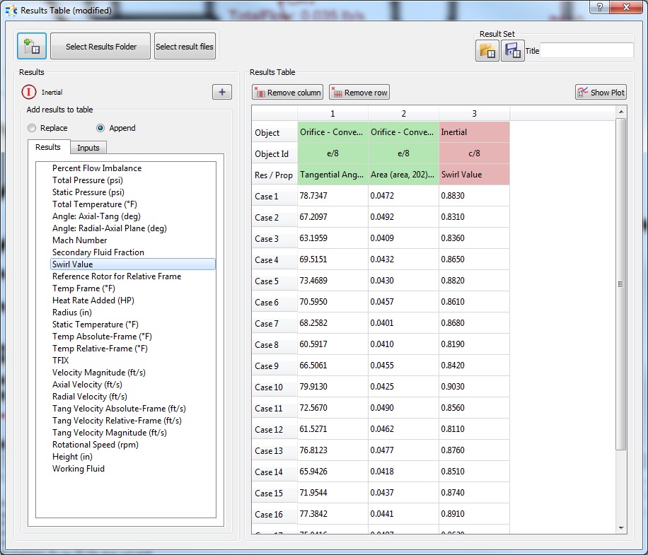
Figure 1.07:Results Table showing Tangential Angle and Swirl Value
- Choose Swirl Value
- Highlighting two columns and clicking show plot will create a line a plot of both
values and also a “Scatter Plot” button. Clicking that button will create a plot
seen in Figure 1.08
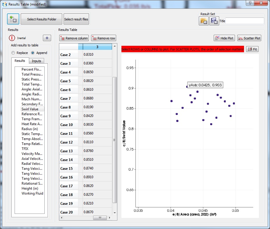
Figure 1.08: Scatter plot of swirl value vs area
- Hovering over the points will show the values from the table that correspond to the point