Tutorial 1: Simple Stationary Flow Network Modelling
Purpose/Objective
This exercise will walk the user through building a simple, three element flow circuit using basic chamber and element types based on the defined geometry. The user will learn how to:
- Drag and drop entities onto the screen in order to create the network
- Edit chamber properties
- Edit element properties
- Check the model
- Run the model
- Post-process the model
- Chamber Types: Plenum
- Element Types: Standard Tube, Conventional Orifice
- Fluid: Air
Geometry:
Flow network simulates air flowing through a long pipe with a 1/2“ inner diameter into a large tank. The air then exits the tank through 2 exits.
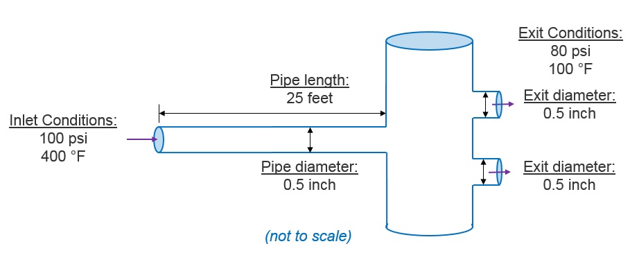
Figure 1.01: Simple Stationary Model Chamber Layout
Step 1: Create Model Entities
- Drag and drop three boundary plenums and one non-boundary plenum from the Object Tree to the Graphical Workspace. See figure 1.02
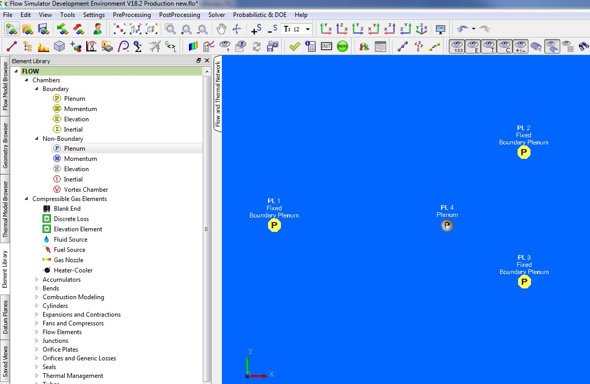
Figure 1.02: Simple Stationary Model Chamber Layout
- Drag and drop tube element, and connect upstream chamber to boundary chamber 1, and downstream chamber to non-boundary chamber 4.
- Drag and drop two orifice elements, each one connecting upstream to non-boundary chamber 4 and to each of the remaining boundary chambers. See Figure 1.03.
- Save new model database by selecting File → Save As, and specifying a filename.
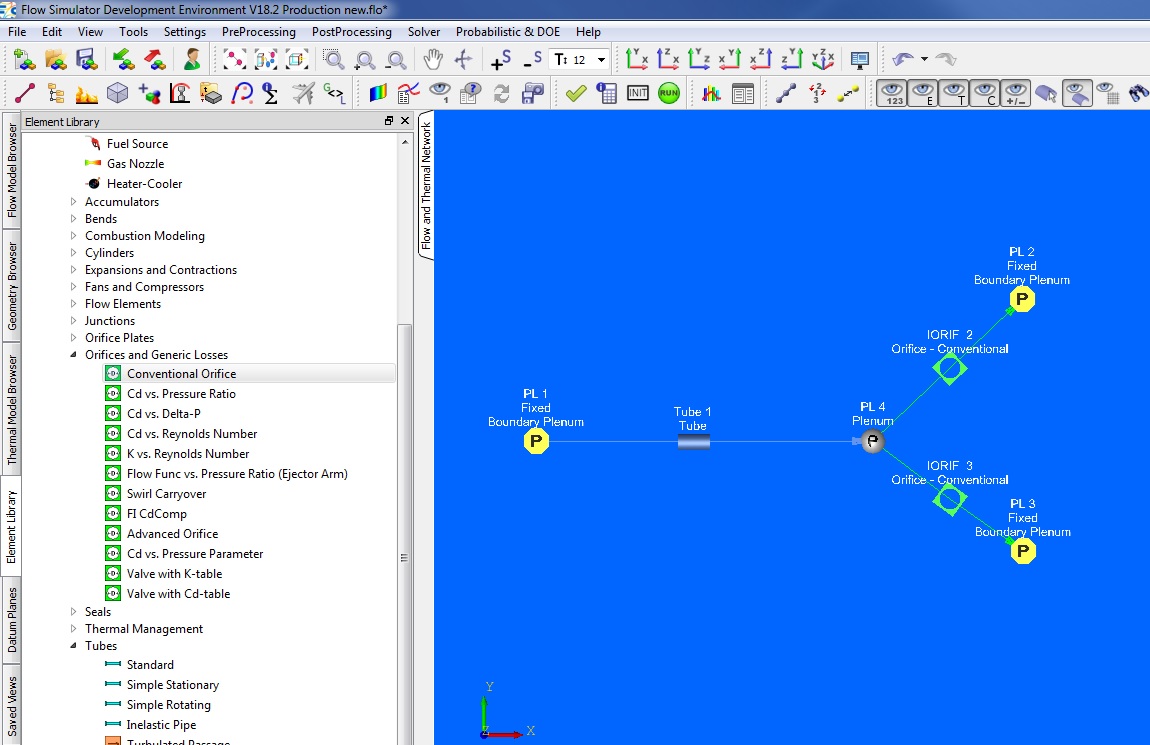
Figure 1.03: Simple Stationary Model, Chambers and Elements
Step 2: Modify Entity Properties
- Select boundary chamber 1 (inlet), and set static pressure to 100 psi and relative total temperature to 400 F.
- Select both (shift + click) boundary chambers 2 and 3 (exits).Set static pressure to 80 psi and relative total temperature to 100 F.
- Select tube element. Set diameter to 0.5in, length to 25ft, and turn Heat Transfer to adiabatic (under Advanced Options → Heat Addition).
- Select both (shift + click) orifice elements. Set diameter to 0.5in (may have to switch Area/Diameter drop down to Diameter first), and Cd to 0.65.
- Save database by selecting the save icon in the upper left corner of the toolbar

Step 3: Check Model and Run
- Select checkmark icon from the top toolbar
 to check the model for warnings/errors.
- An error should populate stating that the internal chamber has not been initialized
- Select the initialization icon from the toolbar
 , and pick Start. Accept values once flow solver has
converged.
, and pick Start. Accept values once flow solver has
converged. - Select run icon from toolbar
 . Run Flow Simulator.
Step 4: Post-process
- Results file (*.res) should automatically be loaded into GUI. If not, it can be selected via File → Load Result File
- By default, both chamber and elemental results are displayed in the graphical workspace. See Figure 1.04.
- Customization of the displayed results is accessible within Settings → Display Options
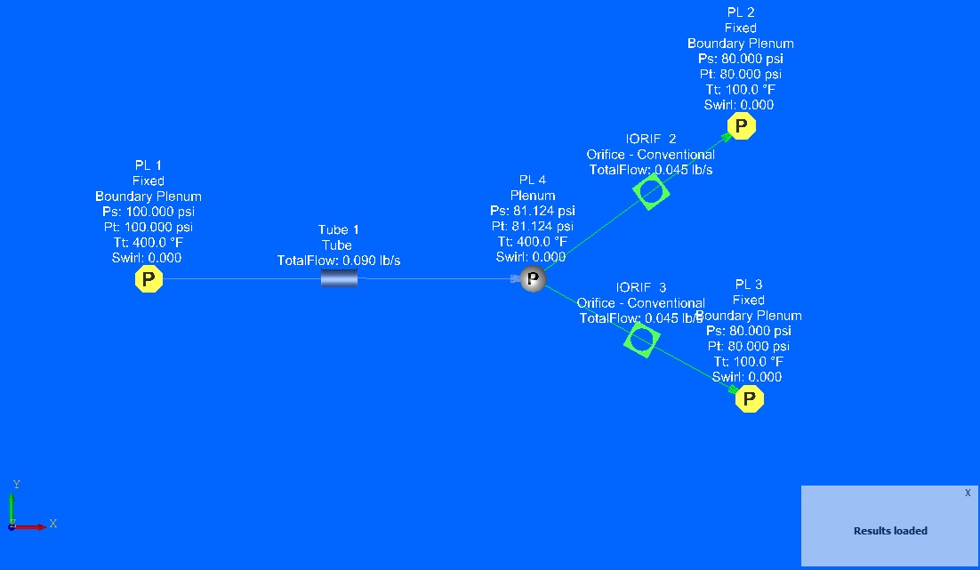
Figure 1.04: Simple Stationary Model w/ Results Displayed
Model Folder Contains
| simple_stationary.JPG | Image file |
| simple_stationary.flo | Flow Simulator ASCII-based database file. |
| simple_stationary.res | ASCII-based Flow Simulator results file. This can be loaded into Flow Simulator to view chamber and elemental solution data |
| convhist_fi.out | ASCII-based convergence output from Flow Simulator solution. |