Tutorial 5: Simple Cavity Model
Purpose/Objective
This exercise will walk the user through building a simple rotor/stator model with the use of cavities. The user will learn how to:
- Edit chamber properties
- Edit element properties
- Edit cavity properties
- Check the model
- Run the model
- Post-process the model
- Chamber Types: Plenum, Inertial, Vortex
- Element Types: Forced Vortex, Conventional Orifice, FI CdComp Orifice
- Fluid: Air
Step 1: Examine geometry
- The user will be creating a flow model of a cavity located between a rotating and a stationary component.
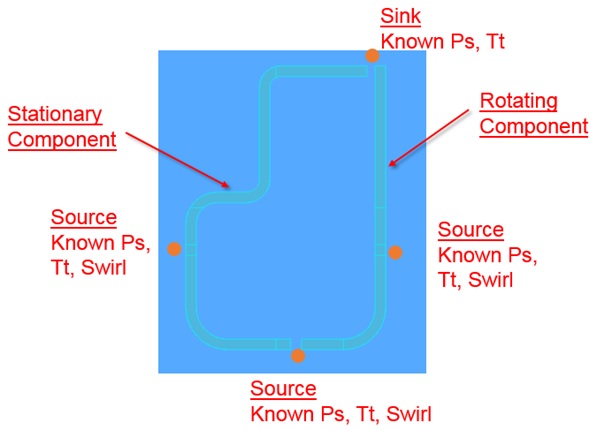
Figure 1.01: Simple Cavity
- The geometry consists of a stationary component on the left and a rotating component on the right. Air comes into the cavity through the bottom gap and the side holes and then exits through the top gap (shown in Figure 1.01)
Step 2: Load IGES file
- Go to File → Load IGES File
- Browse to IGES location and select open (Rotor_Stator_Surface.igs)
Step 3: Building Model
- Plan model setup based on what is known about the geometry
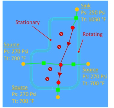
Figure 1.02: Sketch/Outline of cavity model
- Drag and drop Boundary Plenum chambers at the inlet and outlet locations from Figure
1.02
- Translate (right click chamber/element → translate) option and manually editing the coordinates (Property Editor → Location), can be used to assist in placing chambers and elements in the right location
- Use
 to adjust symbol and text size
 - Place non-boundary inertial chambers at the center of the cavity and one at the top and bottom gaps
- Connect conventional orifice elements between the stator boundary plenum (left) and the center inertial chamber, between the bottom boundary plenum and the bottom inertial chamber, and between the top boundary plenum and top inertial chamber
- Connect a FI CdComp orifice between the rotor boundary plenum (right) and the center
inertial chamber
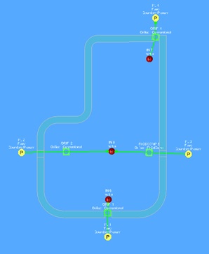
Figure 1.03: Initial model setup
- Connect the inertial chambers with Forced Vortex (Cavity of present) elements
- Place Vortex Chambers at the locations shown in Figure 1.02
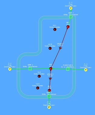
Figure 1.04: Vortex chamber and element placement
- For the three inlet boundary plenums
- Set pressure to 270 psi
- Set temperature to 700 F
- For the sink boundary plenum
- Set pressure to 250 psi
- Set temperature to 1050 F
- For the bottom inlet conventional orifice
- Set area to 2.35 in
- Set Cd to 0.75
- Set Hide Advanced Options → Element Orientation → Element Inlet Orientation to Radial Outward
- Set Hide Advanced Options → Rotation Effects → Rotor Index to Rotates with Air and set Radius to 1.75 in
- For the stator conventional orifice
- Set area to 9.03 in
- Set Cd to 0.75
- Set Hide Advanced Options → Element Orientation → Element Inlet Orientation to Other and set Tangential Angle to 45 degrees
- For the rotor CdComp orifice
- Set area to 9.03 in
- Set length to 0.25 in
- Set Hydraulic Diameter to 0.25 in
- Set Hide Advanced Options → Rotation Effects → Rotor Index to Rotor 1 and set Radius to 3.875 in
- Set Hide Advanced Options → Element Orientation → Element Inlet Orientation to Other and set Tangential Angle to 180 degrees
- Set Part Surface Angle → Tangential to 180 degrees
- For the top conventional orifice
- Set area to 12.56 in
- Set Cd to 0.75
- Set Hide Advanced Options → Element Orientation → Element Inlet Orientation to Radial Outward
- Set Hide Advanced Options → Rotation Effects → Rotor Index to Rotates with Air and set Radius to 8 in
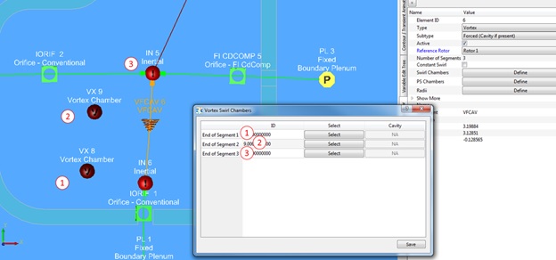
Figure 1.05: Bottom Vortex element Swirl Chambers setup
- For the bottom Forced Vortex element
- Set Number of Segments to 3
- Define Swirl Chambers as shown in Figure 1.05
- Define Radii as shown in Figure 1.06

Figure 1.06: Bottom Vortex element Radii setup
- For the top Forced Vortex element
- Set Number of Segments to 3
- Define Swirl Chambers as shown in Figure 1.07
- Define Radii as shown in Figure 1.08
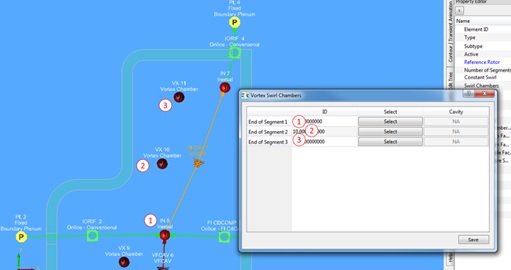
Figure 1.07: Top Vortex element Swirl Chambers setup
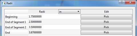
Figure 1.08: Top Vortex element Radii setup
- Plan to configure cavities as shown below
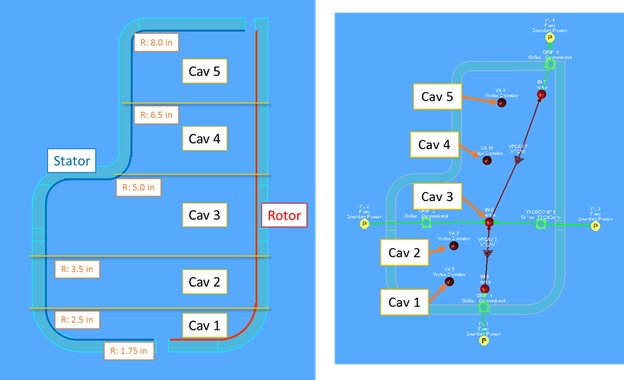
Figure 1.09: Sketch/Outline of cavity setup
- Right click on the Cavity 1 vortex chamber and select Create Cavity
- Name it Cav_1 and click OK
- Go to the Cavity Property Editor
- Create a new surface
- Select Stationary from the dropdown menu and click OK
- Move the radial button to Create under Coordinates and click the locations shown in Figure 1.10 (After creating the point by clicking, the coordinates can be edited in the text box)
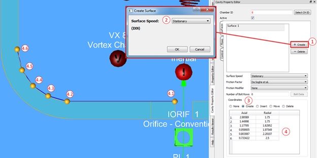
Figure 1.10: Creating stator cavity surface
- Create a new surface
- Follow the same steps to create the cavity 1 rotor surface, except this time select
Rotor 1 as the surface speed in the pop up box (Figure 1.11)
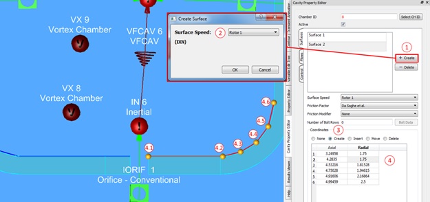
Figure 1.11: Creating rotor cavity surface
- Under Cavity Property Editor, select the flows tab and set it up as shown in Figure 1.12
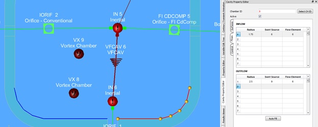
Figure 1.12: Cavity 1 flows input
- Repeat these steps for the remaining four cavities and reference the pictures below
for input setup
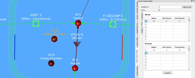
Figure 1.13: Cavity 2 flows input
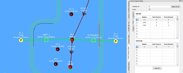
Figure 1.14: Cavity 3 flows input
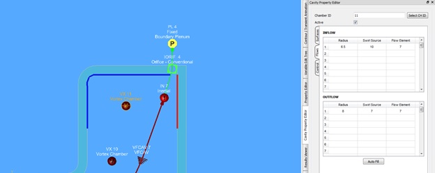
Figure 1.15: Cavity 4 flows input
Figure 1.16: Cavity 5 flows input
- Once complete, cavity setup can be verified by going to the Flow Model Browser tab
on the left and right click → Show All on Cavities. This will highlight the rotor
and stator surfaces as shown in Figure 1.17
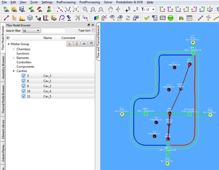
Figure 1.17: All cavity surfaces shown
- Open Analysis Setup
 -->Reference
Conditions
-->Reference
Conditions- Set Shaft #1 Rotor Speed (RPM) to 5000 and save
- Set Show More -> Chamber Swirl -> Rotor Index to Rotor 1 for all inertial chambers
- Set Show More -> Chamber Swirl -> Rotor Index to Rotor 1 for all boundary plenums
- For the bottom gap boundary plenum, set Show More -> Chamber Swirl → For Forward Flow to 0.5
- For the rotor (right) boundary plenum, set Show More → Chamber Swirl -> For Forward Flow to 1
Step 4: Check Model and Run
- Select checkmark icon from the top toolbar
 to check the model for warnings/errors.
- An error should populate stating that the internal chamber has not been initialized
- Select the initialization icon from the toolbar
 , and pick Start. Accept values once flow solver has
converged.
, and pick Start. Accept values once flow solver has
converged. -
Select run icon from toolbar
 . Run Flow Simulator
Step 5: Post-process
- Results file (*.res) should automatically be loaded into GUI. If not, it can be selected via File → Load Result File
- By default, both chamber and elemental results are displayed in the graphical workspace.
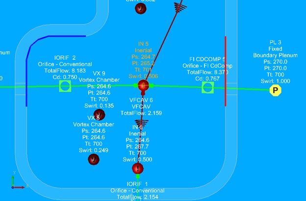
Figure 1.18: Cavity model results