Tutorial 6: High Pressure Turbine (HPT) Stage 1 Blade (S1B) cooling air supply
Purpose/Objective
This exercise will walk the user through building a flow model of a High-Pressure Turbine (HPT) Stage 1 Blade (S1B) cooling air supply circuit for a gas turbine. The user will learn how to:
- Edit chamber properties
- Edit element properties
- Edit cavity properties
- Check the model
- Run the model
- Post-process the model
- Chamber Types: Plenum, Inertial, Vortex
- Element Types: Forced Vortex, Conventional Orifice, FI CdComp Orifice, Vermes Seal
- Fluid: Air
Step 1: Examine geometry
- The user will be creating a flow model of the air passages that supply cooling air to a S1B.
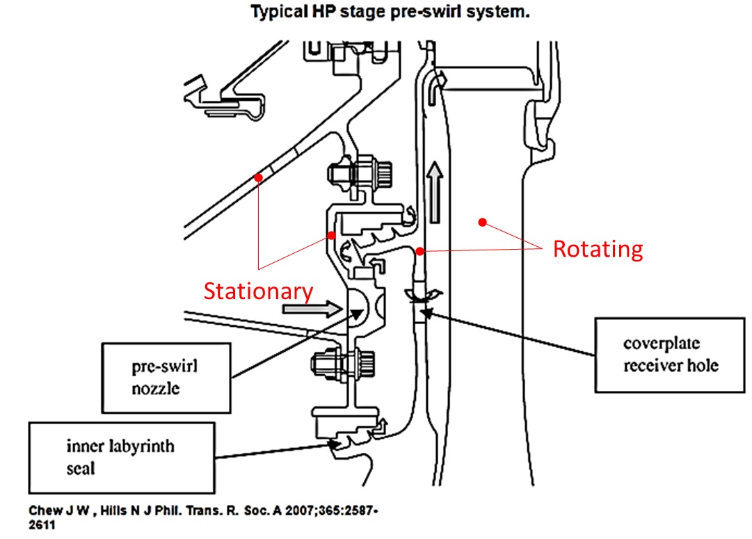
Figure 1.01: S1B Supply
- The flow will go through a series of passages requiring the use of vermes seal elements as well as the creation of cavities for the swirl resulting from the interaction between rotating and stationary parts leading up to the inlet of the S1B cooling supply (shown in Figure 1.01)
Step 2: Load IGES File
- Click File → Load IGES File
- Browse to IGES location and select open (S1B_supply.igs)
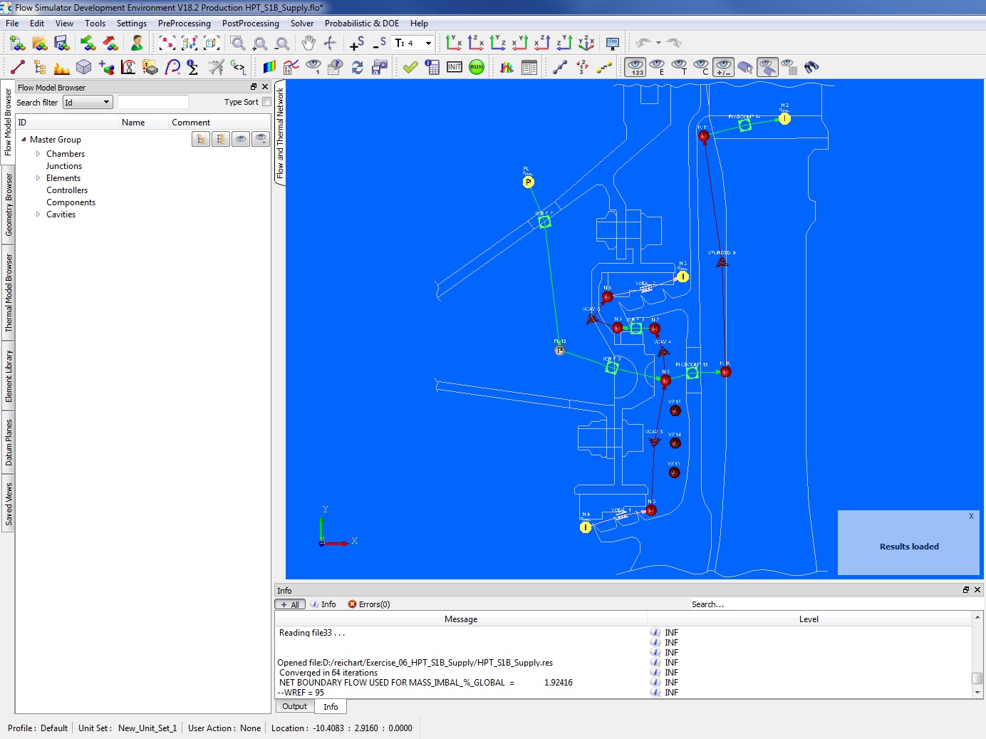
Figure 1.02: Loading IGES File
Step 3: Building Model
- Plan model setup based on what is known about the geometry
-
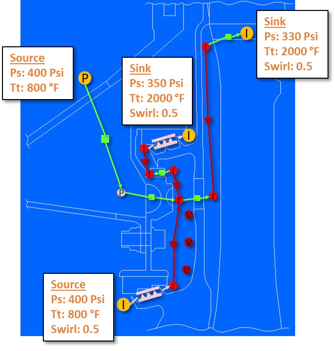
Figure 1.03: Sketch/Outline of S1B supply model
- Drag and drop Boundary Plenum and Inertial chambers at the inlet and outlet
locations from Figure 1.03
- Translate (right click chamber/element → translate) option and manually editing the coordinates(Property Editor → Location), can be used to assist in placing chambers and elements in the right location
- Use
 to adjust symbol and text size
 - Place non-boundary inertial chambers at the locations shown in Figure 1.03
- Place a non-boundary plenum at the location shown in Figure 1.03
Figure 1.04: Chamber placement
- Place vermes seal elements at the labyrinth seal locations
- Place cavity vortex elements between the two labyrinth seal locations and use a
forced vortex element for the flow feeding up to the S1B (Figure 1.05)
Figure 1.05: Vortex element placement
- Place conventional orifice and FI CdComp elements as shown in Figure 1.06
Figure 1.06: Initial model setup
- Define the vermes seal elements as shown in Figure 1.07
- When defining individual tooth seal clearances for the top vermes seal use the “Remove Row” button to bring the number of rows down to three
Figure 1.07: Vermes seal element setup
- For conventional orifice 1 (Figure 1.06), set diameter to 0.3 in
- Set Cd to 0.8
- Set Hide Advanced Options → Element Multiplicity → No. of Streams Entering and Exiting to 20
- For conventional orifice 2 (Figure 1.06), set diameter to 0.24 in
- Set Cd to 0.75
- Set Hide Advanced Options → Element Multiplicity → No. of Streams Entering and Exiting to 12
- Set Hide Advanced Options → Element Orientation → Element Inlet Orientation to Other and set Tangential Angle to 70 deg
- For conventional orifice 3 (Figure 1.06), set diameter to 0.2 in
- Set Cd to 0.6
- Set Hide Advanced Options → Rotation Effects → Rotor Index to Rotates with Air and set Radius to 4.99 in
- For CdComp orifice 1 (Figure 1.06), set Area to 0.38 in^2
- Set Length to 0.12 in
- Set Hydraulic Diameter to 0.38 in
- Select Fillet under Corner Type and apply a Corner Radius of 0.01 in
- Set Hide Advanced Options → Element Multiplicity → No. of Streams Entering and Exiting to 12
- Set Hide Advanced Options → Rotation Effects → Rotor Index to Rotor 1 and set Radius to 4.6 in
- Set Hide Advanced Options → Rotation Effects → Swirl Carryover to Fixed Swirl Carryover and set Swirl Carryover to 0.9
- For CdComp orifice 2 (Figure 1.06), set Area to 0.03 in^2
- Set Length to 0.7 in
- Set Hydraulic Diameter 0.25 in
- Set Hide Advanced Options → Element Multiplicity → No. of Streams Entering and Exiting to 24
- Set Hide Advanced Options → Rotation Effects → Rotor Index to Rotor 1 and set Radius to 6.8 in
- Place three vortex chambers as shown in Figure 1.03
- Define cavity vortex element 1 (Figure 1.05) as shown in Figure 1.08 and Figure
1.09
Figure 1.08: Cavity Vortex element 1 setup
Figure 1.09: Cavity Vortex element 1 setup
- Define cavity vortex element 2 (Figure 1.05) as shown in Figure 1.10
Figure 1.10: Cavity Vortex element 2 setup
- Define cavity vortex element 3 (Figure 1.05) as shown in Figure 1.11
Figure 1.11: Cavity Vortex element 3 setup
- For forced vortex element 1 (Figure 1.05) check Constant Swirl and set Swirl Forward
and Reverse to 0.8
- Set Radii → Beginning to 4.6 in
- Set Radii → End to 6.8 in
- Plan to define cavities as shown in Figure 1.12
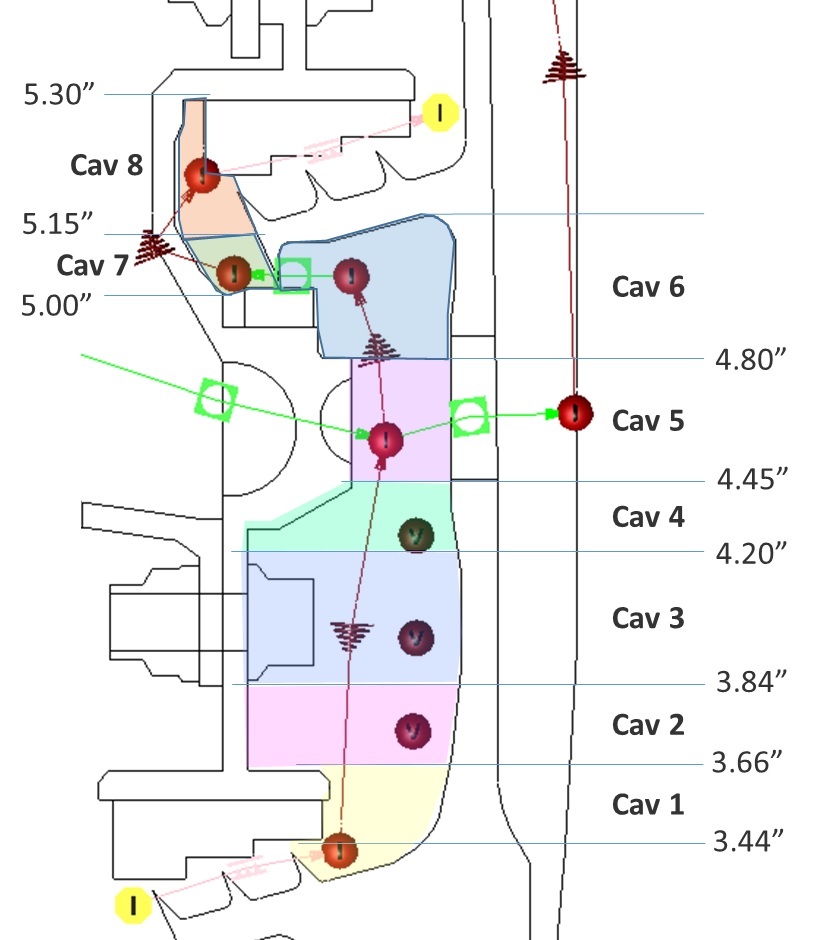
Figure 1.12: Cavity layout
- For Cavity 1, right click on the inertial chamber at the exit of the labyrinth seal,
select Create Cavity, and name it Cav 1
- Go to the Cavity Property Editor tab and create three surfaces as shown Figure 1.13
- Switch Surface 1 Friction Modifier from “None” to “Friction Multiplier” and enter a Friction Multiplier Value of 2
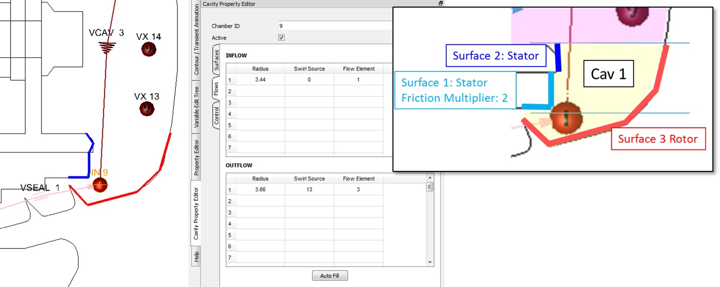
Figure 1.13: Cavity 1 setup
- Set up Cavity 2 as shown in Figure 1.14
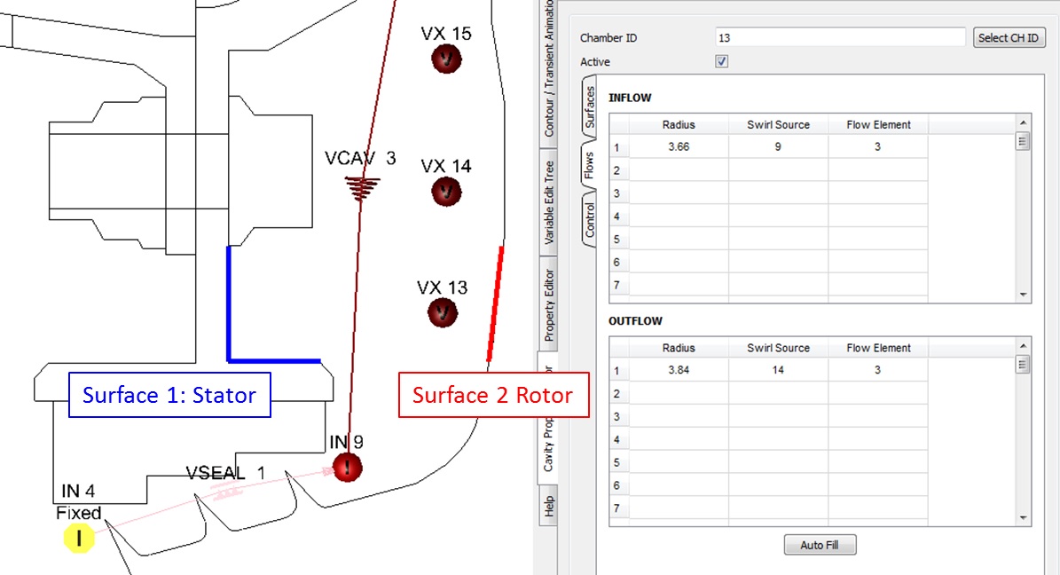
Figure 1.14: Cavity 2 setup
- Set up Cavity 3 as shown in Figure 1.15
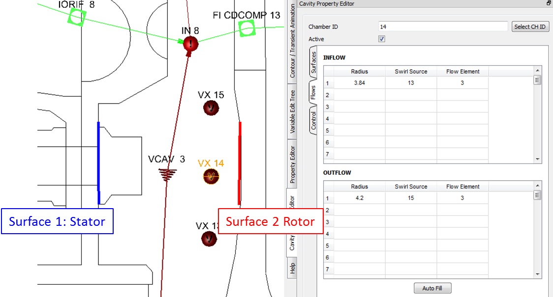
Figure 1.15: Cavity 3 setup
- Set up Cavity 4 as shown in Figure 1.16
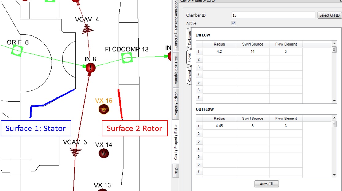
Figure 1.16: Cavity 4 setup
- Set up Cavity 5 as shown in Figure 1.17
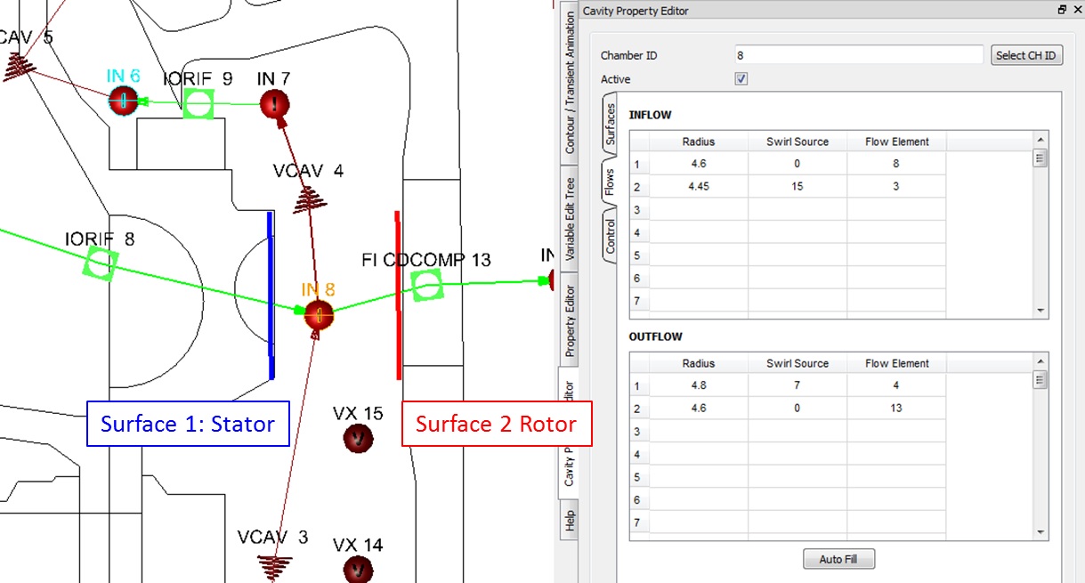
Figure 1.17: Cavity 5 setup
- Set up Cavity 6 as shown in Figure 1.18
- Switch Surface 2 Friction Modifier from “None” to “Friction Multiplier” and enter a Friction Multiplier Value of 2
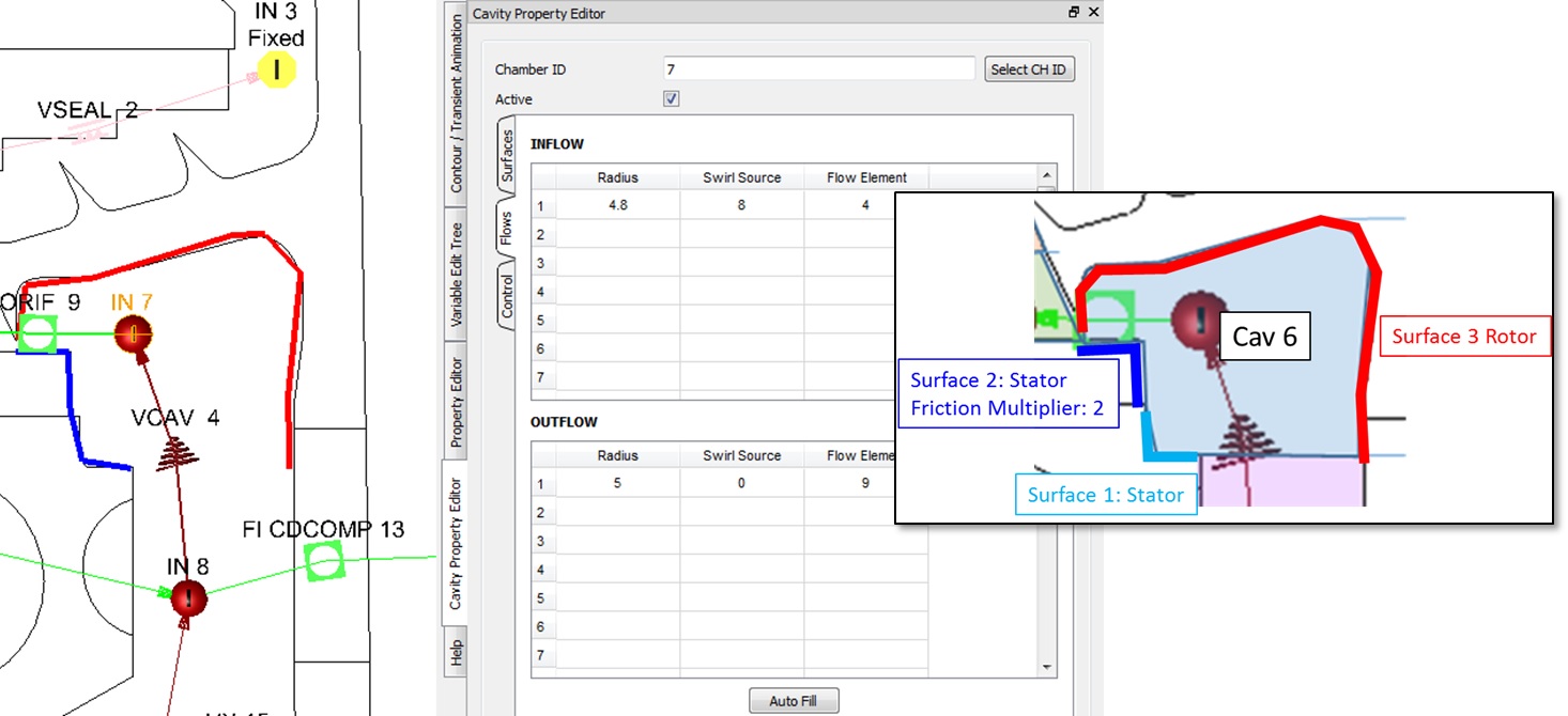
Figure 1.18: Cavity 6 setup
- Set up Cavity 7 as shown in Figure 1.19
- Switch Surface 1 Friction Modifier from “None” to “Friction Multiplier” and enter a Friction Multiplier Value of 2
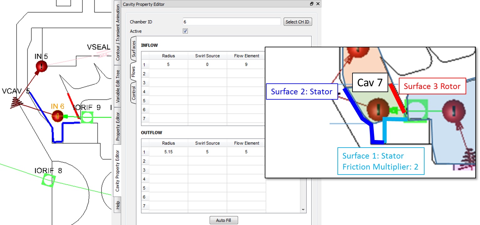
Figure 1.19: Cavity 7 setup
- Set up Cavity 8 as shown in Figure 1.20
- Switch Surface 2 Friction Modifier from “None” to “Friction Multiplier” and enter a Friction Multiplier Value of 2
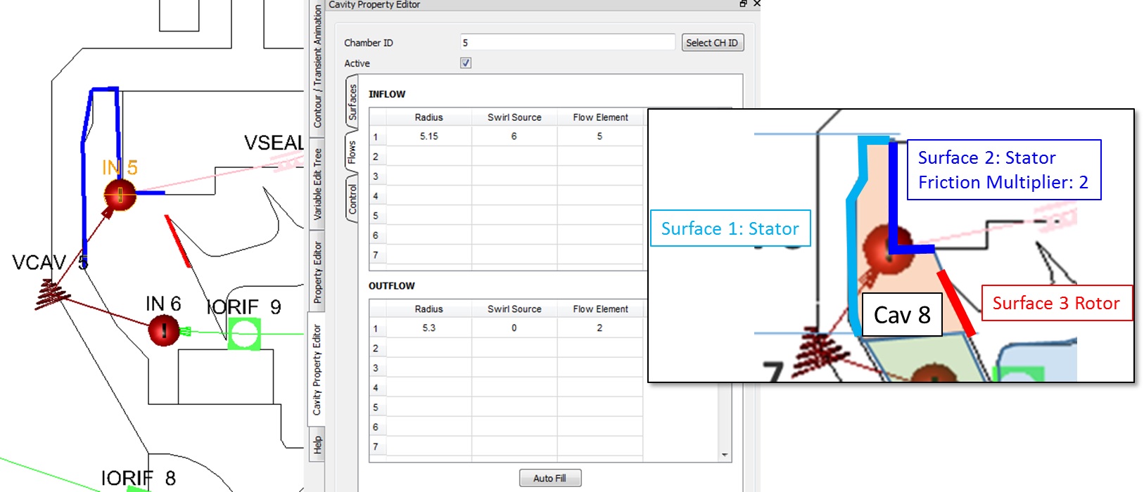
Figure 1.20: Cavity 8 setup
- Under Solver → Analysis Setup → Reference Conditions, set Shaft #1 Rotor Speed (RPM)
to 10000
- Set Reference Flow Rate to 95 lb/s
- For all internal and boundary inertial chambers, set Show More → Chamber Swirl
→Rotor Index to Rotor 1
- Set Show More → Chamber Swirl → For Forward Flow to 0.5
- Set Show More → Chamber Swirl → For Reverse Flow to 0.5
- Set up chamber boundary conditions as shown in Figure 1.03
Step 4: Check Model and Run
- Select checkmark icon from the top toolbar
 to check the model for warnings/errors.
- An error should populate stating that the internal chamber has not been initialized
- Select the initialization icon from the toolbar
 , and pick Start. Accept values once flow solver has
converged.
, and pick Start. Accept values once flow solver has
converged. - Select run icon from toolbar
 . Run Flow Simulator.
Step 5: Post-process
- Results file (*.res) should automatically be loaded into GUI. If not, it can be selected via File → Load Result File
- By default, both chamber and elemental results are displayed in the graphical
workspace.
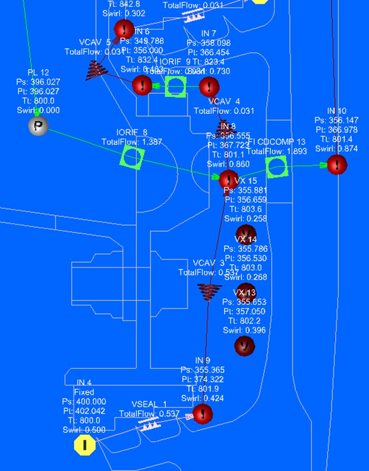
Figure 1.18: S1B supply model results
Results displayed after running the model will include pressures, temperatures, and swirl values