Tutorial 13: Cross Flow Heat Exchanger Model
Purpose/Objective
This exercise will walk the user through building a simple three pass cross flow heat exchanger model with air as cold side fluid and oil as hot side fluid.
The user will learn how to:
- Edit chamber properties
- Edit heat exchanger properties
- Check the model
- Run the model
- Post-process the model
- Chamber Types: Plenum
- Element Types: Link, Plate Fin Heat exchanger, Orifice
- Fluid: Air, Oil
Step 1: Building Modelp
- Plan model setup based on number of passes
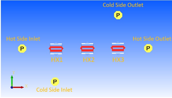
Figure 1.01: Sketch/Outline Heat exchanger model
- Drag and drop boundary Plenum chambers at the inlet and outlet locations for cold
and hot side as shown in Figure 1.01
- Translate (right click chamber/element → translate) option and manually editing the coordinates (Property Editor → Location), can be used to assist in placing chambers and elements in the right location
- Use
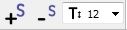 to adjust symbol and text size
 - Drag and drop three heat exchangers as we are modeling three pass heat exchangers
- Hot side:
- Connect incompressible conventional orifice elements between the inlet boundary plenum (left) and the first heat exchanger (HX1) to capture inlet manifold pressure loss
- Connect incompressible link element between the first (HX1) and second heat exchanger (HX2), between the second (HX2) and third heat exchanger (HX3) to transfer data between heat exchanger elements without any additional pressure or heat loss
- Connect incompressible fixed flow element between third heat exchanger (HX3) and outlet plenum chamber (right) to maintain fixed flow at hot side
- Cold Side:
- Connect compressible conventional orifice elements between inlet boundary plenum (bottom) and first heat exchanger (HX1) to model inlet manifold pressure loss, between third heat exchanger (HX3) and outlet boundary plenum (top) to model outlet manifold pressure loss
- Connect compressible conventional orifice element between first heat exchanger (HX1) and second heat exchanger (HX2), between second heat exchanger (HX2) and third heat exchanger (HX3) to model turning pressure loss
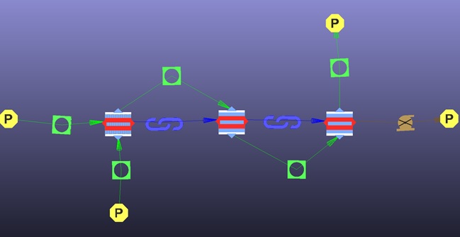
Figure 1.02: Compressible and incompressible orifice, fixed flow and link Elements Placement
- Inlet boundary plenum for cold side
- Set pressure to 200 psi
- Set temperature to 200 F
- Set material to Air (Ideal gas)
- Outlet boundary plenum for cold side
- Set pressure to 199.9 psi
- Set temperature to 250 F
- Set material to Air (Ideal gas)
- Inlet boundary plenum for hot side
- Set pressure to 100 psi
- Set temperature to 500 F
- Set material to MIL-L-7808 Oil (L)
- Outlet boundary plenum for hot side
- Set pressure to 99.9 psi
- Set temperature to 350 F
- Set material to MIL-L-7808 Oil (L)
- For orifice element between hot side inlet plenum (left) and first heat exchanger
(HX1)
- Set Area to 3 sq.in
- Set Cd to 0.85
- For orifice element between inlet boundary plenum (bottom) and first heat exchanger
(HX1) and between third heat exchanger (HX3) and outlet boundary plenum (top)
- Set Area to 4 sq.in
- Set Cd to 0.85
- For orifice element between first heat exchanger (HX1) and second heat exchanger
(HX2), between second heat exchanger (HX2) and third heat exchanger (HX3)
- Set Area to 6 sq.in
- Set Cd to 0.80
- For Fixed flow element between third heat exchanger (HX3) and hot side outlet
plenum
- Set Mass flow rate to 1 lb./s
- For heat exchangers
- Set Length in X direction to 12 in
- Set Length in Y direction to 12 in
- Set Length in Z direction to 40 in
- Set Flow Configuration to Cross flow
- For heat exchangers Cold Side Fin Details
- Set Fin Type as Offset Fins
- Set Material to Stainless Steel
- Set Fins Per Inch to 20
- Set Plate Spacing to 0.1 in
- Set Fin Thickness to 0.004 in
- Set Offset Length to 1.2 in
- Set Plate Material to Stainless Steel
- Set Plate Thickness to 0.02 in
- Set Bar/End Plate Thickness to 3 in
- For heat exchangers Hot Side Fin Details
- Set Identical Fin Type and Geometry for Hot Side to No and
- Set Fins Per Inch to 20
- Set Plate Spacing to 0.1 in
- Set Fin Thickness to 0.004 in
- Set Offset Length to 1.2 in
Note: Setting Identical Fin Type and Geometry for Hot Side to YES will set the required settings same with Cold Side Fin Details
Step 2: Check Model and Run
- Select check mark icon from the top toolbar
 to check the
model for warnings/errors.
to check the
model for warnings/errors. - Select run icon from toolbar
 . Run Flow Simulator.
Step 3: Post-process
- Results file (*.res) should be generated in model running directory.
- open the result file (*.res) and search for HX element. Results for heat exchanger
will have following data
- Inlet and outlet information for cold and hot side of heat exchanger with
fluid properties
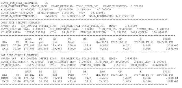
- Inlet and outlet information for cold and hot side of heat exchanger with
fluid properties