Tutorial 7: Transient Flow Analysis using Feed Forward Controller Model
Purpose/Objective:
This exercise will show the user how to create a Feed Forward Controller that will adjust a valve opening position based on the valve upstream pressure. The user will learn how to:
- Create a Feed Forward Controller
- Setup a transient run
- Check the model
- Run the model
- Post-process the model
- Elements used: Conventional Orifice, Standard Tube, Ball Valve, FFWD Controller, Generic Fixed Volume Accumulator.
Step 1: Create plan
- The goal of this exercise is to determine time it takes a volume to pressurize up to
400 psi from a small leak and then how long it takes to depressurize the volume
after a valve is opened by a feed forward controller.
- Volume initial pressure = 14.7 psi
- Fluid = air; Use compressible gas elements
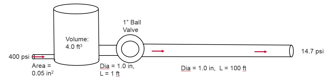
Figure 1.01: Model Plan
Step 2: Building Model
- Create Chambers (2 Boundary Plenum and 2 Internal Momentum) and the
Accumulator
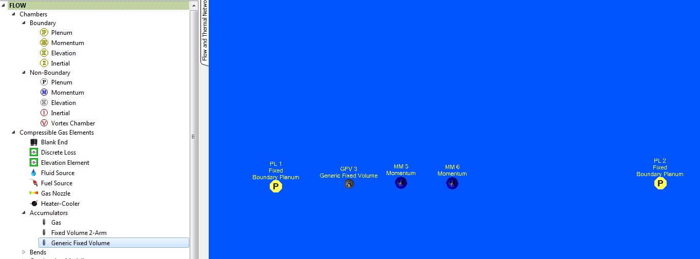
Figure 1.02: Chamber and Accumulator
- Create Elements: 1 Conventional Orifice, 2 Standard Tubes, and 1 Ball Valve

Figure 1.03: Elements
- Create Feed Forward Controller
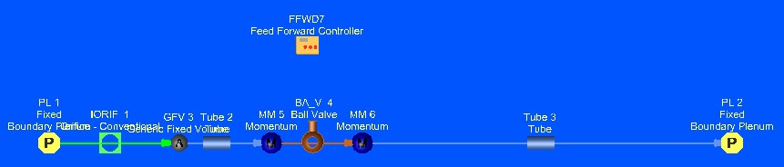
Figure 1.04: Feed Forward Controller
- Assign Chamber Pressure and Temperature
- Upstream Boundary Plenum: P= 400 psi, T= 80 F
- Downstream Boundary Plenum: P= 14.7 psi, T= 80 F
-
2 Internal Momentum: Ptotal = 14.7 psi and Pstatic = 14.7 psi, T=80F.
These are the initial conditions for the transient.
- Assign Accumulator Properties: Total Volume = 4 ft3
- Chamber Initialization for the accumulator: Plenum, Pstatic = 14.7 psi, T = 80F
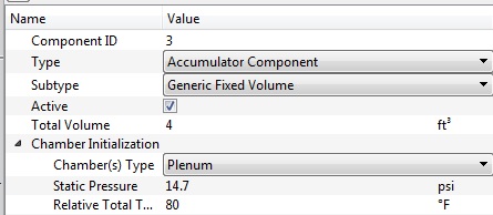
Figure 1.05: Accumulator Properties
- Assign Element properties
- Orifice: Area = 0.05 in2
- Upstream Tube: Dia = 1 in., Length = 1 ft, Heat Transfer = Adiabatic
- Downstream Tube: Dia = 1 in, Length = 100 ft, Heat Transfer = Adiabatic
- Ball Valve: Pipe Dia = 1 in, Valve Position = 0% open (controller will adjust this)
- Assign Feed Forward Controller Properties
- Controller will use a python script.
# Valve position will be set to 100% open if the upstream pressure> 400 psi.
# After the valve position is 100% open it will stay 100% open until the run ends.
if VALVEPOS_CUR == 0.0:
if PS > 400:
VALVEPOS_NEW=100
else:
VALVEPOS_NEW=0
else:
VALVEPOS_NEW=100
- Controller will use a python script.
- Copy and Paste or retype the text. Lines with # are comments. Python uses indentation to identify control logic (if and else statements).
- 2-gauge variables: Upstream pressure and the ball valve position
- Ball valve position will be used as a gauge and manipulated variable.
- 1 manipulated variable: the ball valve position
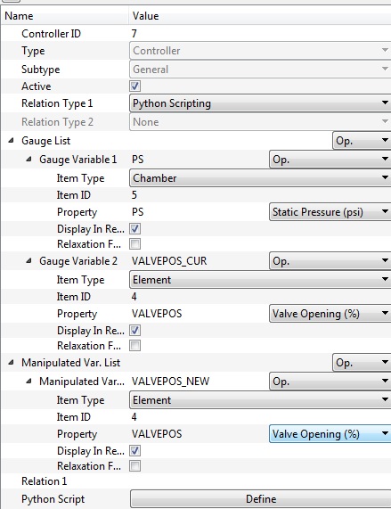
Figure 1.06: FFWD Controller properties
- Analysis Setup:
- Analysis Type: Transient Flow
- Initial Condition Option: User-defined Pressure and Temperature Data
- Solver will use P and T that have been assigned to the 2 internal momentum chambers and the accumulator for the time = 0 sec. solution.
- Transient Run Control Parameters (Figure 1.07)
- Run Start Time: 0 sec
- Run Stop Time: 100 sec
- Solution Time Step Option: Automatic Time Stepping
- Initial, Minimum and Maximum Time Step: 0.01, 0.1, 0.5 sec
- Output Time Step Option: Constant Output Intervals
- Output Time Step: 0.5 sec
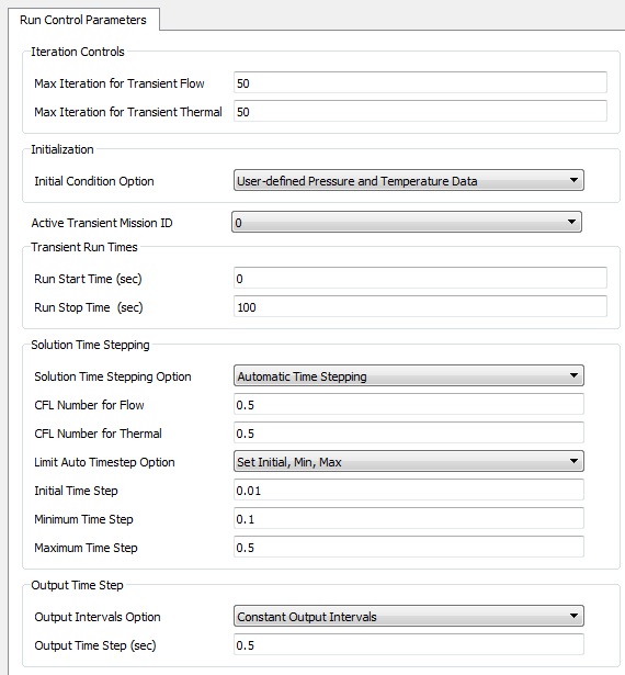
Figure 1.07: Transient Run Control Parameters
Step 3: Check Model and Run
- Select checkmark icon from the top toolbar
 to check the model for warnings/errors.
- No errors or warnings should appear.
- Select run icon from toolbar
 . Run Flow Simulator.
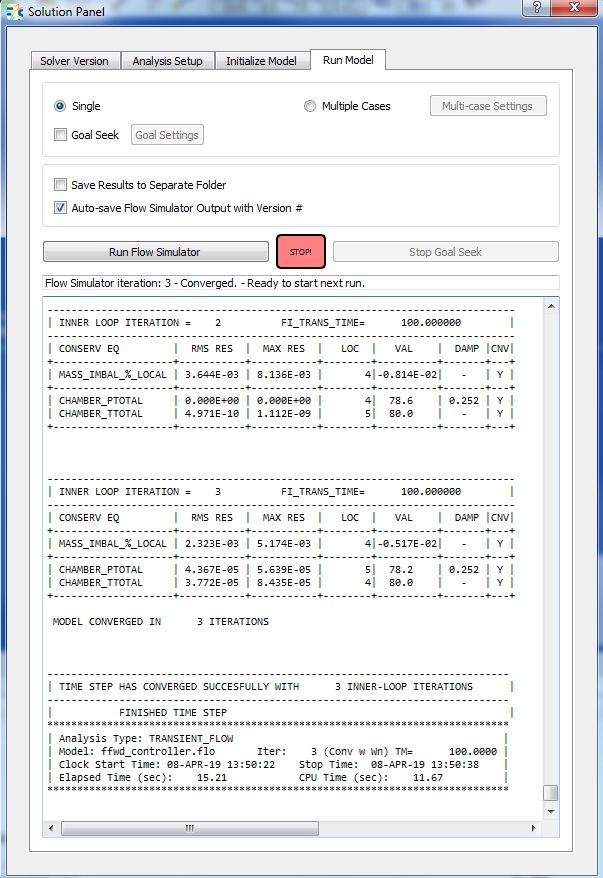
Figure 1.08: Run Panel
Step 4: Post-process
- The first results file (*.res) of the transient should automatically be loaded into GUI. If not, it can be selected via File → Load Result File
- By default, both chamber and elemental results are displayed in the graphical
workspace.
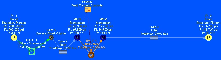
Figure 1.09: Results at 0.5 seconds
- Use the Results Table for post processing results Versus Time.
- Pick the Accumulator Static Pressure
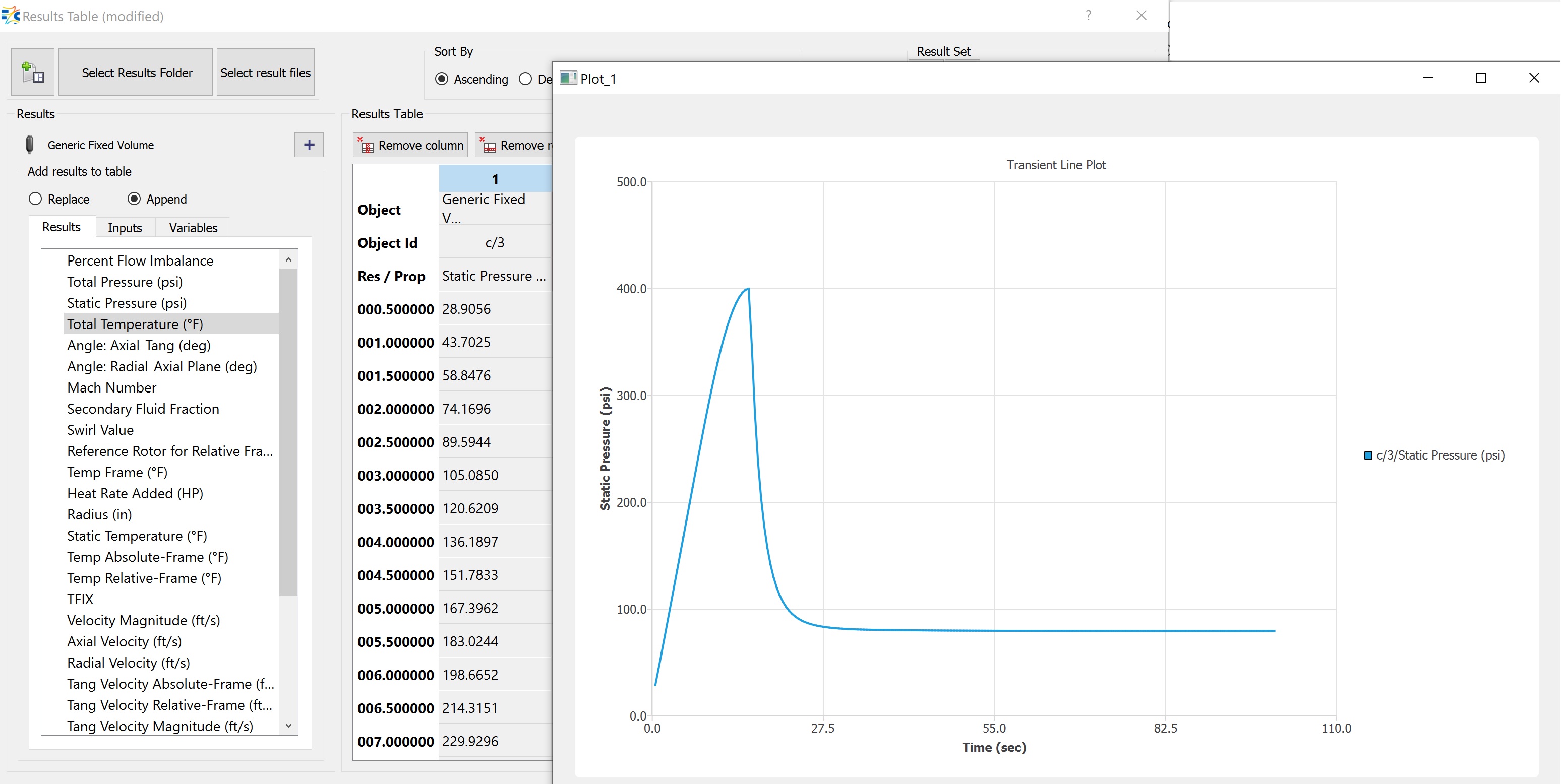
Figure 1.10: Accumulator Static Pressure versus Time
- Pick the Orifice element upstream of the accumulator and the tube downstream
and plot Total Flow
Figure 1.11: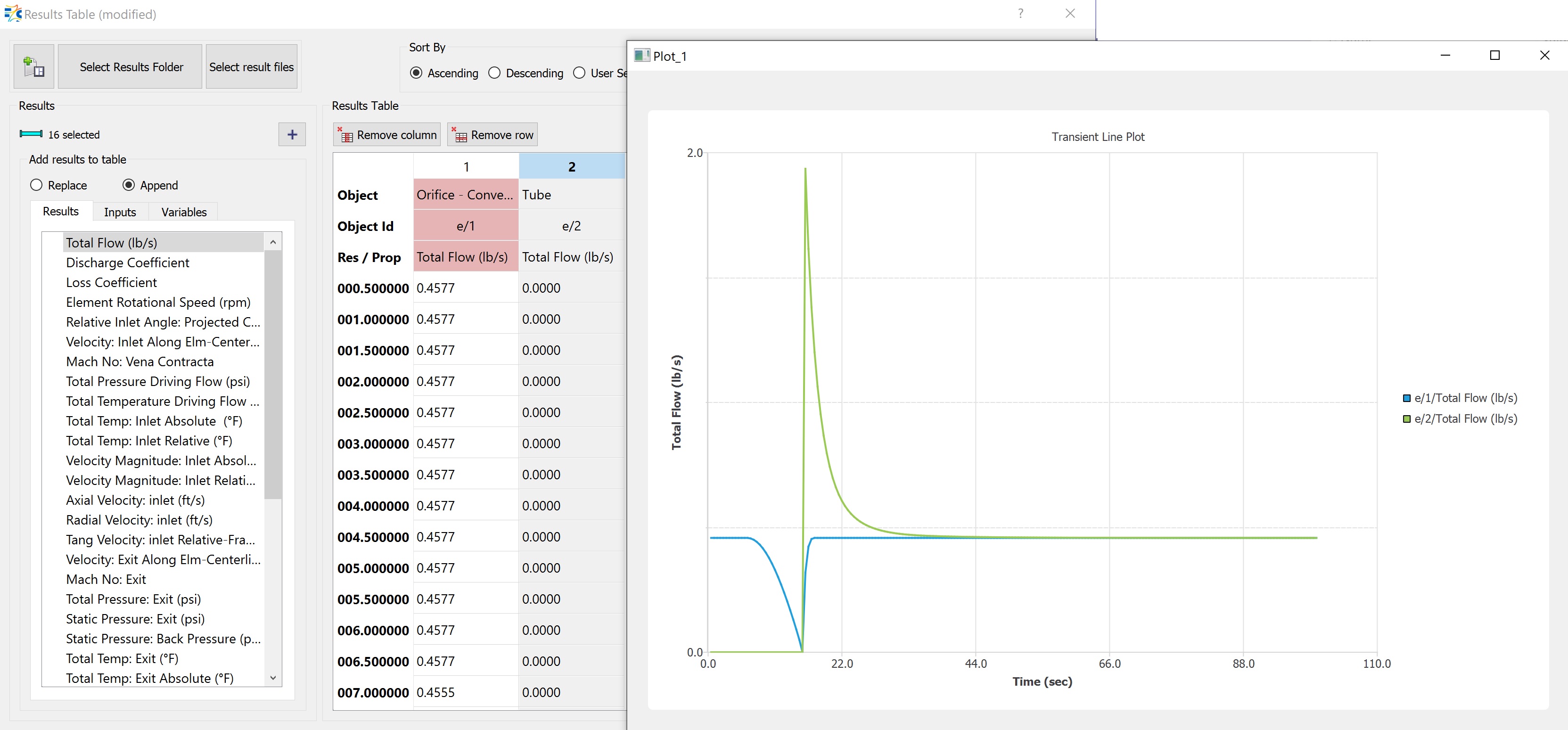
- Pick the Accumulator Static Pressure